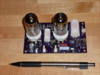
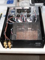
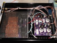
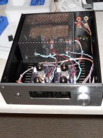
I've been tinkering with this for a while, finally have it assembled and working.
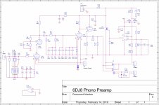
6DJ8 Ultralinear cascode in the front (37dB gain), passive RIAA, 6DJ8 plate follower (29db gain) directly coupled into a cathode follower. 46db total gain at 1kHz. Opamp and MOSFET shunt regulator on each channel amp PCB. Surface mount 1% resistors and SMT 2% film caps except for the HV and large value LV electrolytics. Only 2 caps in the signal path, both Mundorf Polypropylene.
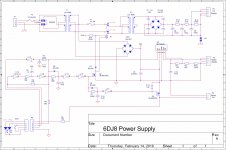
Power supply uses two 7V toroid trafos connected back to back for heater supply and HV. Hex inverter provides ½ sec debounce and input toggle switching as well as 15 second delay for HV activation and additional 5 second delay to switch the outputs active. Tricolor LED in panel mount switch turns red when heater supply is on, green when speakers connected.
Cabling is RG318 double shielded silver braid with teflon dielectric.
Low noise, 0.06% distortion at 5mV input (mostly second harmonic). Very natural sounding; complex passages sound less cluttered, hearing individual details and instruments that previously went undetected. Yadi-Yadi-Yada, blah, blah, blah, etc., etc.....
Comments, suggestions, critiques welcomed.....
6DJ8 Ultralinear cascode in the front (37dB gain), passive RIAA, 6DJ8 plate follower (29db gain) directly coupled into a cathode follower. 46db total gain at 1kHz. Opamp and MOSFET shunt regulator on each channel amp PCB. Surface mount 1% resistors and SMT 2% film caps except for the HV and large value LV electrolytics. Only 2 caps in the signal path, both Mundorf Polypropylene.
Power supply uses two 7V toroid trafos connected back to back for heater supply and HV. Hex inverter provides ½ sec debounce and input toggle switching as well as 15 second delay for HV activation and additional 5 second delay to switch the outputs active. Tricolor LED in panel mount switch turns red when heater supply is on, green when speakers connected.
Cabling is RG318 double shielded silver braid with teflon dielectric.
Low noise, 0.06% distortion at 5mV input (mostly second harmonic). Very natural sounding; complex passages sound less cluttered, hearing individual details and instruments that previously went undetected. Yadi-Yadi-Yada, blah, blah, blah, etc., etc.....
Comments, suggestions, critiques welcomed.....
Attachments
Last edited:
Nice! And nicer still to see someone else on the cascode bandwagon.. 
Consider evaluating dc stability with R5 connected to the plate supply rather than the plate of the upper tube in the cascode. From an AC standpoint it's still a classic cascode.
I have also used grid leak bias on the upper tube, works well but you can't be assured of a consistent operating point with all tubes selected.
I connected the upper cascode bias to the plate instead of the DC supply to improve the PSRR. I loose ~6dB of gain by doing this (ultra-linear vs box standard Cascode), but the distortion goes down and the PSRR goes from nil to 22dB. The higher PSRR may not be needed. Bypassing R16 in the opamp feedback path improves the noise rejection of the shunt supply down to <10Hz. I measured the noise floor on one of the amplifier PCBs at ca. -90dB (ref 0dBV output).
I'm puzzled by the ultra-linear connection since that 2.2uF capacitor should be down -3dB or so by 0.3Hz so effectively there can't be any AC feedback to the grid to the 6DJ8. Did I misread that capacitor value or is it much smaller than the schematic seems to imply?
My cascode front ends have a theoretical and measured PSRR of about 1dB which as you have remarked requires a very quiet supply. (It's quite a challenge to get something super quiet)
An improvement to 22dB PSRR would be monumental if achieved.
I have achieved SNRs in the high 80s in some designs using 6S3P (Russian) and D3A types. Cartridge thermal noise becomes a limiting factor.. (Probably best compromise is HOMC, but I much prefer LOMC or strain gauges.)
Really nice design however, and I'm thrilled to be discussing this with the only other person here who seems to do original tube based phono stage design.
The cap value is 2U2; the loss of gain may have to do with the lower voltage (130VDC vs 250VDC) and change in bias/operating point; the 6dB lower gain was measured. The 22dB PSRR came from simulation (TubeCad); I haven't measured it, but I find their simulations to be spot on in most cases. The other benefit of the UL connection is the (simulated) output impedance drops from 30K to 3K.
I'm also running fairly low current (1.75mA), so I'm not operating at a very linear part of the curve, but the output voltage excursion is small the UL connection improves distortion somewhat.
I'm also running fairly low current (1.75mA), so I'm not operating at a very linear part of the curve, but the output voltage excursion is small the UL connection improves distortion somewhat.
Last edited:
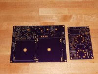
Gerber files and BOM files attached.
This circuit uses High Voltages in excess of 300VDC which can be lethal. Do not attempt this project unless you are skilled in working on high voltage assemblies.
The heatsink for the MIC29502 heater supply will be difficult to solder to the PCB as I eliminated the thermal reliefs on the top and bottom of the PCB. Remove the mounting pins from the heatsink and cut threads in the channel using a chip-less 4-40 tap; secure the heatsink to the PCB with 4-40 screws. Likewise there are no thermals on the MIC29502 ground pin, the minus side of the bridge rectifier or the 10KUfd filter cap. All of these were necessary to remove in order to reduce power supply ripple on the heater supply. I used a 2oz copper PCB for the power supply.
There is a small solder jumper on the 6DJ8 PCB next to the input for the heater supply that needs to be bridged with solder. This will connect the heater supply ground to the HV and signal supply ground at a single point. It was done this way to isolate the heater currents from signal ground plane. The jumper must be in place or the shunt regulator will not function.
There is a push on jumper (JP1) on the power supply board that will connect the HV ground to the AC supply safety ground. In my application, connecting the 2 grounds together reduced hum, but it can also float if need be.
R15 on the 6DJ8 PCB is a 1.8K 3W Metal Oxide flameproof power resistor; do not substitute any other part for this component. If the shunt reg were to short, the entire HV supply will be across this resistor. There is a 3A slo-blo fuse on the LV side of the HV step up transformer that should open if the HV supply is shorted.
I used Gold Lion 6DJ8 tubes as they apparently have a higher voltage spec than the standard variety 6DJ8, particularly for the max voltage across the tube as well as cathode to heater voltage. Use any other tube at your own risk.
Attachments
Last edited:
It was somewhat of a balancing act to get the level of current needed through the tubes, and the operating points of the PF to directly couple to the CF. It could probably be reworked to lower the B+ voltage, but it would require changing all the plate and cathode resistors as well as R15-R18 on the shunt regulator. If you have TubeCAD software, it definitely makes the job easier.
Also, I don't know that the operating voltages are outside of standard 6DJ8 tubes, but they might run very close, particularly the CF which will have ~130VDC across the tube.
Also, I don't know that the operating voltages are outside of standard 6DJ8 tubes, but they might run very close, particularly the CF which will have ~130VDC across the tube.
- Status
- This old topic is closed. If you want to reopen this topic, contact a moderator using the "Report Post" button.
- Home
- Source & Line
- Analogue Source
- YAPP...Yet Another Phono Preamp