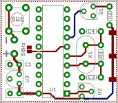
OK, added optional voltage regulator IC3 (bridge jumper if not used), moved the Q10/Q12/Q13 jumpers to the bottom layer and crunched everything together as tight as I could. The board is now 1.1" x 1.8".
Very cool Bill!
Once again great job! Any upload to Oshpark?
")
If there aren't any more changes, I'll output the Gerber files and upload to OshPark.
The link to OshPark: www.oshpark.com/shared_projects/gLJYkSxc
The PCB is 1.1" x 1.8"; cost is $9.90 for 3 pcs.
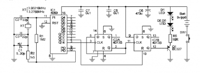
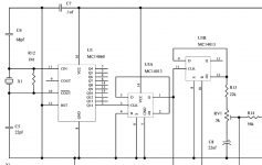
Schematic is attached and is the same as in post #8 as provided by coolmaster: http://www.diyaudio.com/forums/analogue-source/320593-help-please-turntable-100hz-strobe.html#post5384486.
C1 (variable cap) is NOT included on the PCB.
If IC3 regulator is not needed, bridge the solder jumper adjacent to it to bypass.
Bridge one and only one of the bottom side jumpers on IC1 to shorten the duty cycle. Pin 2: Q13 Pin 1: Q12 Pin 15: Q10.
Strobe.zip contains the GerberX274 files if you want to use your own board house.
BOM:
C6 is 6.3mm diameter, 2.5mm lead spacing
Resistors are 1/8W, same series as the SG4 resistors
C2 and C3 are 5mm lead spacing ceramic caps, same series as the SG4 caps
C7 & C8 are 2.5mm lead spacing, same series as the SG4 caps
SW1 is the same tact switch as the SG4
IC3 is LM78L09 series regulator in TO92 package
Q1 is BC327 PNP transistor or equivalent with CBE pinout
The link to OshPark: www.oshpark.com/shared_projects/gLJYkSxc
The PCB is 1.1" x 1.8"; cost is $9.90 for 3 pcs.
Schematic is attached and is the same as in post #8 as provided by coolmaster: http://www.diyaudio.com/forums/analogue-source/320593-help-please-turntable-100hz-strobe.html#post5384486.
C1 (variable cap) is NOT included on the PCB.
If IC3 regulator is not needed, bridge the solder jumper adjacent to it to bypass.
Bridge one and only one of the bottom side jumpers on IC1 to shorten the duty cycle. Pin 2: Q13 Pin 1: Q12 Pin 15: Q10.
Strobe.zip contains the GerberX274 files if you want to use your own board house.
BOM:
C6 is 6.3mm diameter, 2.5mm lead spacing
Resistors are 1/8W, same series as the SG4 resistors
C2 and C3 are 5mm lead spacing ceramic caps, same series as the SG4 caps
C7 & C8 are 2.5mm lead spacing, same series as the SG4 caps
SW1 is the same tact switch as the SG4
IC3 is LM78L09 series regulator in TO92 package
Q1 is BC327 PNP transistor or equivalent with CBE pinout
Attachments
Last edited:
I'm so happy and excited you delivered the best and fully appreciate your kind effort. Its not difficult to build this as long as this pcb is available.
Thank you so much Bill.
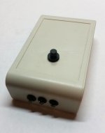
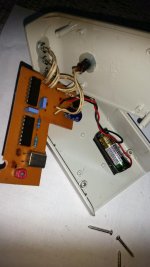
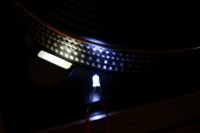
On another note, this is what I built ages ago. Nothing much to look at and what I could do at that time at home. The pcb is home made, not the best quality but sufficient to do the job for purpose and intent. I didn't use any tact switch, hardwired to a suitable soft push momentary button switch, finally powered by a 23A/12V battery. This battery cell is good to go. I chose this plastic enclosure as I find it comfortable and easy to mount everything including 3 bright white LED's. Its time for a new creation.
Thank you so much Bill.
On another note, this is what I built ages ago. Nothing much to look at and what I could do at that time at home. The pcb is home made, not the best quality but sufficient to do the job for purpose and intent. I didn't use any tact switch, hardwired to a suitable soft push momentary button switch, finally powered by a 23A/12V battery. This battery cell is good to go. I chose this plastic enclosure as I find it comfortable and easy to mount everything including 3 bright white LED's. Its time for a new creation.
Attachments
If you click on the link, they have both 50Hz and 60Hz strobes. They work with strobe disks for 100Hz and 120Hz, and they also have downloadable discs.
Thank you, just tried it. What a pity that he seems to be out of business at the moment.
Best regards!
Didn't realize they were shut down.
If someone wants to build their own microprocessor based strobe, the attached files will allow you to do so.
The OshPark Link for the PCB is: www.oshpark.com/shared_projects/mYkuTiHJ
The PCB is 1.25" x 1.1" and cost $6.85 for 3 pcs.
The uP is an Atmel AT89C2051 in a 20 pin DIP package.
The crystal is 3.6864MHz in an HC49US package.
C1 and C2 are the same 0.1uFd caps in the SG4 project.
C3 and C4 are 22pfd ceramic caps, same series as the 10pfd in the SG4 project.
U2 is the same reset controller (DS1833-15) as the SG4 project.
SW1 is the same tact switch as the SG4 project.
Q1 is the same MOSFET xstr as the SG4 project Q1-Q4.
The resistors are 1/8W, same series as the SG4 project. R1 is 1M0.
U3 is an LM78L05 series in TO92 package.
The LEDs are mounted straddling the PCB; The lead on the flat side of the LED is on the top of the PCB. Resistor R2 is 150 Ohms for 1 LED, 82 Ohms for 2 LEDs and 47 Ohms for 3 LEDs (assuming Red LEDs with a 2.1V forward drop).
The duty cycle is fixed at 16:1 so the on time is 625uS for 50Hz and 521uS for 60Hz.
A solder jumper on the PCB selects 60Hz (120Hz) if open and 50Hz (100Hz) is bridged.
Strobe3.zip has the Gerber X274 files if you want to use your own board house.
Strobe Source.zip has the 8051 assembly source code, hex and bin files to program the uP. I will not be distributing the uP or programming them. If someone wants to take these files and run with it, knock yourself out.
Attachments
An Arduino Nano & LED combo would allow you to program the pulse as narrow as you liked.
That is the easiest solution and is very accurate if the code is right
That's the problem with using the Arduino. Unless you disable the timer used by the OS, you will never get the accuracy you need to do this.
If someone wants to build their own microprocessor based strobe, the attached files will allow you to do so.
What a pleasant surprise to see this, Bill is super again! My thanks and appreciation for your super effort for all here.
There's something I overlooked and noticed about the Vinyl Engine strobe the documentation, something there which I've to double check and confirm later on. If there's any consequence I will report back later.
The author mentioned at the beginning the schematic prior to March 06 is wrong but the pcb artwork is correct. What is available for download there is Feb 06 documentation. Its possible the schematic I posted here earlier could be with some error. I regret in the midst of excitement of this project, I didn't notice this earlier and thought everything is correct.
Bill, any thoughts?
Lee
it was a mistake:
Pin 8 of the CD4060 must be grounded. Pin 10 should connect ONLY to the two resistors.
Yes, I was reading about it earlier today while researching this issue. The author's pcb had a error too, the LED's were marked the wrong way round at his component overlay. The author seemed to have submitted and updated document to be replaced but apparently not done, its still the Feb 06 document there.
Its much to my relief I posted the correct schematic here and hoped Bill checked and approve the schematic as correct while designing the pcb.
Meanwhile I was looking at Linn Valhalla motor controller schematic and its very similar the VE strobe.
Attachments
Its much to my relief I posted the correct schematic here and hoped Bill checked and approve the schematic as correct while designing the pcb.
I did not prototype the circuit to check it; it appeared to be drawn correctly so I did the CAD work to reflect the schematic that coolmaster posted (with the exception of the multiple jumpers for duty cycle control and the regulator that terrom requested). Hopefully it is correct.
I did prototype the uP based version and verified the hardware/firmware works very well for both 50/60Hz.
The PWM functions are useful for precise timing:That's the problem with using the Arduino. Unless you disable the timer used by the OS, you will never get the accuracy you need to do this.
Accurate Arduino Clock | ContractorWolf.com
Thanks for the link. It uses the PWM clock to trigger an interrupt, but this will still suffer from jitter and inaccuracy due to the OS timer. The interrupt service routine that counts the PWM pulses cannot be vectored to if the OS timer has already called its ISR. The ATMega328 processor has only one level of interrupt priority, so any interrupts that occur while one is already being processed will have to wait. IME, this is a severe limitation with this design when critical timing is involved.
I haven't dug into the PWM mechanism of the ATMega328; if the clock generation for the PWM output is independent of the other hardware, it may be possible to configure it to output a 120Hz square wave with a 16:1 duty cycle directly. With 8 bit PWM at 16MHz, the prescaler would not be an integer value, so the crystal would need to be changed to 15.72864 MHz for a prescaler of 256 or 7.86432 Mhz for a prescaler of 128.
All of this is moot, as doing this in assembly language on an 8051 core is trivial; the code space for AT89C2051 example takes up less space than the header text and the chips cost <$1 in 1 pc qtys. With a 3.6864MHz xtal, it produces exactly 100/120Hz with a 1/16 duty cycle with no jitter.
Thanks for the link. It uses the PWM clock to trigger an interrupt, but this will still suffer from jitter and inaccuracy due to the OS timer. .
If you use a PIC micro it automatically reloads the PWM registers at the end of the cycle.
You can also use push buttons to set the PWM rate.
SETUPPWM
;SET UP PWM OUTPUT AT 21KHZ
BANKSEL PR2
MOVLW 43 ;SETS UP TIMER 2 PERIOD THIS GIVES 22KHZ PWM FRAME PERIOD
MOVWF PR2
MOVLW 4
MOVWF T2CON
MOVLW 0XC ;PWM MODE
MOVWF CCP1CON
MOVLW 0
MOVWF CCPR1L ;FORCE OFF AS PICKIT3 DOESNT RESET PIC FULLY.
RETLW 0
Yes Nigel, you can use the PWM mechanism to generate a fixed duty cycle pulse train directly, but getting it to do it at 100/120Hz rate may not be possible without the use of prescaling and changing the xtal.
The 8051 timers in mode 2 are 8 bit auto-reload so this is handled in hardware and is extremely accurate and jitter free. Using a 3.6864 MHz xtal and a timer count of 192 gives exactly 1600 Hz (100Hz x 16 to create a 1/16 duty cycle) and a count of 160 gives exactly 1920 Hz (120Hz x 16).
The 8051 timers in mode 2 are 8 bit auto-reload so this is handled in hardware and is extremely accurate and jitter free. Using a 3.6864 MHz xtal and a timer count of 192 gives exactly 1600 Hz (100Hz x 16 to create a 1/16 duty cycle) and a count of 160 gives exactly 1920 Hz (120Hz x 16).
Pyramid!
Could you add 4 mounting holes to the pcb? It's located on the 50mmX30mm shape. So it will be possible to use thr pcb in the case.
Use double sided tape.
Also wanted to ask if there is any positive to have an inductor (L1 on the original schematic) on the + of 12V?
I don't see the need for it. It's battery powered, draws little current and is off when not in use.
I ordered both the strobe boards from OSHPark. Wonderful to know that they upgraded my order to swift service due to available room at fabrication process. Feeling excited and wonderful I'll have it sooner than expected. I was also searching around Aliexpress China for some suitable remote enclosures, suitable nice ones seen there. Can't wait to build entirely new strobe light for my use. I really need to learn PCB design and later share it like Bill have done. I may seek kind guidance from experts here for a top quality optimized pcb before its shared.
Last edited:
- Status
- This old topic is closed. If you want to reopen this topic, contact a moderator using the "Report Post" button.
- Home
- Source & Line
- Analogue Source
- Help me please with this turntable 100Hz strobe