I've been designing a nfb jfet phono stage, and I've faced the most obvious problem: how to simulate the cartridge.
I've used the simplest aproach:
Cartridge tests
Hagerman Technology LLC: Cartridge Loading
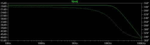
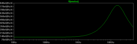
Ltspice simulations show different results using or not the simulated MM cartridge on frequency and noise plot.
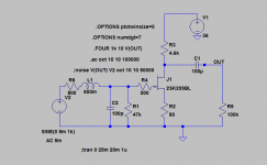
Results without MM cartridge sim:
2sk209 simple.png
2sk209 simple freq plot.png
2sk209 simple noise plot.png
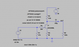
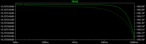
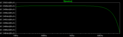
Results with MM cartridge sim:
2sk209 w mm sim.png
2sk209 w mm sin freq plot.png
2sk209 w mm sim noise plot.png
You can see the worse frequency response at high frequencies when you have the cartridge sim on circuit. Also, there's a peak on noise plot (maybe tip resonance? DF96 answer suggests cartridge inductance resonating with capacitive load).
I've used the simplest aproach:
Cartridge tests
Hagerman Technology LLC: Cartridge Loading
Ltspice simulations show different results using or not the simulated MM cartridge on frequency and noise plot.
Results without MM cartridge sim:
2sk209 simple.png
2sk209 simple freq plot.png
2sk209 simple noise plot.png
Results with MM cartridge sim:
2sk209 w mm sim.png
2sk209 w mm sin freq plot.png
2sk209 w mm sim noise plot.png
You can see the worse frequency response at high frequencies when you have the cartridge sim on circuit. Also, there's a peak on noise plot (maybe tip resonance? DF96 answer suggests cartridge inductance resonating with capacitive load).
Attachments
Last edited:
I'm not sure what point you are making. An MM cartridge is designed to give an overall fairly flat response into the specified load (usually 47k plus some parallel capacitance). It balances mechanical and electrical responses to achieve this. Your simulation presumably only models the electrical part of the cartridge, so will give results which will mislead people who don't understand this.
The noise peak you see is almost certainly not tip resonance, as that is a mechanical phenomenon, but the cartridge inductance resonating with the capacitive load.
PS That Hagerman page makes the same mistake: it ignores mechanical issues so arrives at the wrong conclusions. Ignore it.
The noise peak you see is almost certainly not tip resonance, as that is a mechanical phenomenon, but the cartridge inductance resonating with the capacitive load.
PS That Hagerman page makes the same mistake: it ignores mechanical issues so arrives at the wrong conclusions. Ignore it.
Last edited:
So it's better not taking into account this electrical response because it's compensated by the mechanical design of the cartridge, leading to a flat response, if I understand you correctly. In any simulation I can simply put a plain sine wave voltage source to get an estimated result (it's always estimated, of course). Thank you!
No, it's vice versa. You choose the reactive part of the load, i.e. the sum of all capacitances, as of tonearm wiring, signal cable, virtual capacitance of your MM preamp, so that you get flat total response.So it's better not taking into account this electrical response because it's compensated by the mechanical design of the cartridge, leading to a flat Response...
Best regards!
The flat total response includes the MM mechanical response, which you presumably don't know. The solution is to drive the phone preamp from a voltage source (either in simulation or experiment) and engineer the electronics to get the required RIAA response. Then adjust the capacitive and resistive loading at the input point to match whatever your MM needs for a flat overall response.
The only reason for using an MM electrical model is to calculate noise, but for MM this will almost always be good enough anyway so not much need to calculate it.
The only reason for using an MM electrical model is to calculate noise, but for MM this will almost always be good enough anyway so not much need to calculate it.
It is worth reading the bob cordell vinyltrak paper available for a few $ from linear audio CordellAudio.com - VinylTrak™ Preamp he does some interesting analysis on the loading and shows why so few MM actually have a flat response and mostly have a resonant hump followed by a steep roll off. By loading differently you can have a truly flat response, if that is what you want.
The cartridge *designer* combined the mechanical and electrical responses SO-THAT it would give "best result" with the specified 47K plus hundreds-pFd load.
For a tube or an FET, you just give it that input impedance, all will be good.
If you mess with low-gain BJT NFB preamps, cartridge impedance interaction is a real thing, there was at least one paper on this.
The noise-peak is real, though the amplitude depends on L. It seems to not be a big deal, perhaps because it happens in a range where ear response declines from its peak.
- Status
- Not open for further replies.
- Home
- Source & Line
- Analogue Source
- Simple simulation of a MM cartridge