Inspired by Frank Blohbaum’s BestPentode, this phonostage uses the high gm Russian 6F12P pentode/triode valve in a simple passive RIAA topology. Measured gain is 65dB and measured output noise is 0.57mV. The Muscovite Micro sub-title is a nod to the suggestion to use the 6F12P in a phono stage, found in kevinkr’s excellent threads describing his adventures using Russian valves such as the 6S3P.
Signal circuit
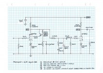
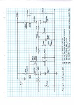
The input device is the pentode (OK, beam tetrode) section of the 6F12P configured as a BestPentode. Described in Linear Audio Vol 0, BestPentode is a variety of cascode in which the screen of the pentode is connected to the emitter of a high voltage BJT (an MPSA44A). The collector is connected to the anode of the pentode, eliminating partition noise.
At the base of the MPSA44A is the junction of a high impedance resistive voltage divider. The lower leg is bypassed by a 4.7uF capacitor to signal ground. The upper leg connects to the anode of the pentode. The voltage at the junction of the MPSA44A sets the pentode screen voltage (see the schematic for measured values).
Grid bias is courtesy of an infrared LED with a measured forward voltage drop of 1.2 V. The anode load is a 10kOhm Caddock thin film resistor.
The all-in-one RIAA eq network is conventional, composed of polypropylene film capacitors and non-inductive wire-wound resistors. All the RIAA network components have high voltage ratings, so I placed the 0.1uF coupling capacitor at the grid of the triode stage. The output impedance of the pentode stage = the anode resistor (10kOhm) which, in series with the first resistor in the network, gives the correct RIAA value.
The triode stage is configured as a common cathode amplifier, with the grid biased by (another) infrared LED and the anode loaded by (another) 10kOhm resistor. It has a relatively high output impedance (estimated at 3.5kOhm) so that high frequencies will roll of if it is asked to drive long interconnects/capacitive loads. I have it driving short (300mm) interconnects.
Power supply
The power transformer, filter choke, filter capacitors and rectifier diodes live in their own ugly steel box made from sheet metal, connected by an umbilical power cord to the ugly steel box made from sheet metal that holds the signal circuits. The supply was designed using PSUDII – the actual voltages are just as PSUDII predicted. The power transformer is a big ugly noisy refugee from someone else’s shed, improved by snubbing using Mark Johnson’s simple-and-brilliant Cheapmodo and my barely credible Tektronics 5103N oscilloscope. The transformer is so noisy that I will replace it – one day.
Voltage regulation
The pentode stage has NO capacity to filter power supply noise. Good regulation is essential and I used Paul Hyne’s impeccable regulators: a high voltage regulator for each channel, a shared regulator for the heater supply.
Measurements
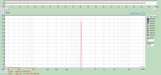
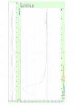
I have attached an Audiotester screen shot showing the output with the cartridge connected and the turntable powered up: the result is output noise of 0.57mV 20Hz to 20kHz. Gain was measured at spot frequencies using a true-RMS benchtop DMM: channel matching was very good (within 2%) and RIAA matching nearly as good.
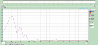
I have attached the Audiotester output when playing the 1kHz 7cm/s reference tone on the Analogue Productions test record (catalogue number AAPT1). The measurement (made with the phonostage output attenuated 12dB so as not to overload the soundcard) is fairly clean, showing a little 2nd harmonic distortion. The cartridge is an Audio Technica 150ML/OCC, the turntable a Denon DP67L.
Sound
Enjoyable – there is no call to return its predecessors to duty. It has run reliably for nearly two years of heavy use.
Warnings and caveats
1: This preamp can produce BIG voltages, enough to kill the input stage of a power amp unless it is a valve stage. Use Zener diodes across the output to limit the voltages. Buy (or borrow) Merlin Blencowe’s excellent hi-fi valve preamp book to find out how.
2: The parameters of all devices vary from sample to sample, batch to batch, and 6F12Ps vary in quality. That said, from six valves I found two pairs that gave the same gain – OK, within 2% of each other.
3: No LTSPICE was harmed in the design of this phono stage – I haven’t learned how to use it and can’t provide models.
4: All measurements were made with my way-less-than-lab-quality tools in my much-closer-to-the-compost-heap-than-the -lab shed. Audiotester was ‘calibrated’ to these exacting standards. All quibbling will provoke amusement and gentle encouragement to build and measure your own.
Acknowledgements
Thanks to Frank Blohbaum and kevinkr for inspiration and encouragement, to Jan Didden for publishing Frank’s idea, and Merlin Blencowe for re-visiting it.
Signal circuit
The input device is the pentode (OK, beam tetrode) section of the 6F12P configured as a BestPentode. Described in Linear Audio Vol 0, BestPentode is a variety of cascode in which the screen of the pentode is connected to the emitter of a high voltage BJT (an MPSA44A). The collector is connected to the anode of the pentode, eliminating partition noise.
At the base of the MPSA44A is the junction of a high impedance resistive voltage divider. The lower leg is bypassed by a 4.7uF capacitor to signal ground. The upper leg connects to the anode of the pentode. The voltage at the junction of the MPSA44A sets the pentode screen voltage (see the schematic for measured values).
Grid bias is courtesy of an infrared LED with a measured forward voltage drop of 1.2 V. The anode load is a 10kOhm Caddock thin film resistor.
The all-in-one RIAA eq network is conventional, composed of polypropylene film capacitors and non-inductive wire-wound resistors. All the RIAA network components have high voltage ratings, so I placed the 0.1uF coupling capacitor at the grid of the triode stage. The output impedance of the pentode stage = the anode resistor (10kOhm) which, in series with the first resistor in the network, gives the correct RIAA value.
The triode stage is configured as a common cathode amplifier, with the grid biased by (another) infrared LED and the anode loaded by (another) 10kOhm resistor. It has a relatively high output impedance (estimated at 3.5kOhm) so that high frequencies will roll of if it is asked to drive long interconnects/capacitive loads. I have it driving short (300mm) interconnects.
Power supply
The power transformer, filter choke, filter capacitors and rectifier diodes live in their own ugly steel box made from sheet metal, connected by an umbilical power cord to the ugly steel box made from sheet metal that holds the signal circuits. The supply was designed using PSUDII – the actual voltages are just as PSUDII predicted. The power transformer is a big ugly noisy refugee from someone else’s shed, improved by snubbing using Mark Johnson’s simple-and-brilliant Cheapmodo and my barely credible Tektronics 5103N oscilloscope. The transformer is so noisy that I will replace it – one day.
Voltage regulation
The pentode stage has NO capacity to filter power supply noise. Good regulation is essential and I used Paul Hyne’s impeccable regulators: a high voltage regulator for each channel, a shared regulator for the heater supply.
Measurements
I have attached an Audiotester screen shot showing the output with the cartridge connected and the turntable powered up: the result is output noise of 0.57mV 20Hz to 20kHz. Gain was measured at spot frequencies using a true-RMS benchtop DMM: channel matching was very good (within 2%) and RIAA matching nearly as good.
I have attached the Audiotester output when playing the 1kHz 7cm/s reference tone on the Analogue Productions test record (catalogue number AAPT1). The measurement (made with the phonostage output attenuated 12dB so as not to overload the soundcard) is fairly clean, showing a little 2nd harmonic distortion. The cartridge is an Audio Technica 150ML/OCC, the turntable a Denon DP67L.
Sound
Enjoyable – there is no call to return its predecessors to duty. It has run reliably for nearly two years of heavy use.
Warnings and caveats
1: This preamp can produce BIG voltages, enough to kill the input stage of a power amp unless it is a valve stage. Use Zener diodes across the output to limit the voltages. Buy (or borrow) Merlin Blencowe’s excellent hi-fi valve preamp book to find out how.
2: The parameters of all devices vary from sample to sample, batch to batch, and 6F12Ps vary in quality. That said, from six valves I found two pairs that gave the same gain – OK, within 2% of each other.
3: No LTSPICE was harmed in the design of this phono stage – I haven’t learned how to use it and can’t provide models.
4: All measurements were made with my way-less-than-lab-quality tools in my much-closer-to-the-compost-heap-than-the -lab shed. Audiotester was ‘calibrated’ to these exacting standards. All quibbling will provoke amusement and gentle encouragement to build and measure your own.
Acknowledgements
Thanks to Frank Blohbaum and kevinkr for inspiration and encouragement, to Jan Didden for publishing Frank’s idea, and Merlin Blencowe for re-visiting it.
Attachments
Hi Bondini!
Can you post a larger schematic as I can't read the values on the one you posted. I suspect others will encounter the same difficulty.
Also if someone needs to drive longer cables have a look at the output circuit in Muscovite Mini III as it will dovetail perfectly with the existing phonospud design.
http://www.diyaudio.com/forums/anal...mini-iii-6n23p-phono-stage-3.html#post4720084
The output impedance is on the order of ohms and very successfully drives over 3 meters of cheap shielded Radio Shack interconnect to my line stage.
Attachments
Hi Bondini,
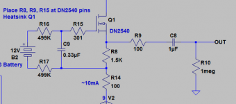
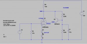
How do you calculate the Ig2 created by the CCS using MPSA44?
I create a simple LTSPICE schematic to simulate the CCS for G2 using a JJ EF806S. The result is an amplification of 28dB. Unfortunately I have no spice model found for the 6F12P to compare the simulation.
best regards
Karsten
How do you calculate the Ig2 created by the CCS using MPSA44?
I create a simple LTSPICE schematic to simulate the CCS for G2 using a JJ EF806S. The result is an amplification of 28dB. Unfortunately I have no spice model found for the 6F12P to compare the simulation.
best regards
Karsten
Attachments
Screen current
Hi karsten21,
I notice that the curves on the data sheet for your pentode show anode current. As they do not show screen current, you will have to estimate it. Typically, anode current is five or six times screen current.
An estimate will do for building a prototype.
Hi karsten21,
I notice that the curves on the data sheet for your pentode show anode current. As they do not show screen current, you will have to estimate it. Typically, anode current is five or six times screen current.
An estimate will do for building a prototype.
You could model a higher anode load
Hi karsten21,
I have just 'eyeballed' the data sheet for your valve - your results look about right to me. I suggest you model a bigger anode resistor and/or higher supply voltage. Try 25kOhm and 250V or 30kOhm and 300V. Gain should increase to 60+ (>35dB).
I do not model in Spice - I don't know if other forum members have a model for the 6F12P. Ufudu kindly tried to trace the curves but ran into trouble. So did the fellow at klausmobile!
Dear bondini,
Thanks a lot for your help ans effort.
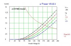
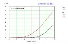
I´m a lucky owner of an utracer ( The uTracer, a miniature Tube Tester / Curve Tracer. ) . In a hurry I measured the JJ EF806 in triode connection. See attached curves. There is also a very nice piece of software available which translate the curves created by utracer to a spice model. I will do this in the next days ( Sorry, I have to work for money the whole day.. so there is not enougth time for realy importand things ).
).
In the meantime I see, that the calculation reound about the MSPA is quite simple. Calculating a Uref for the base of the MPSA ( here using a voltage devider with high overall resistance ). This Uref -0.7V is the desired Ug2.
Thanks a lot for your input!
best regards
Karsten
Thanks a lot for your help ans effort.
I´m a lucky owner of an utracer ( The uTracer, a miniature Tube Tester / Curve Tracer. ) . In a hurry I measured the JJ EF806 in triode connection. See attached curves. There is also a very nice piece of software available which translate the curves created by utracer to a spice model. I will do this in the next days ( Sorry, I have to work for money the whole day.. so there is not enougth time for realy importand things
).In the meantime I see, that the calculation reound about the MSPA is quite simple. Calculating a Uref for the base of the MPSA ( here using a voltage devider with high overall resistance ). This Uref -0.7V is the desired Ug2.
Thanks a lot for your input!
best regards
Karsten
Attachments
From a noise perspective the JJ EF806 is only going to be slightly quieter than the 12AX7A in a phono front end. rp presumably is probably quite high as well - this is the sort of tube I would have chosen a little over a decade ago, since then I have discovered a whole world of very inexpensive, low noise, high transconductance tubes. I highly recommend the Russian 6S3P-EV and the 6S4P-EV, and a handful of them will cost less than a single EF806 and will provide a lot more gain and a lot less noise. (You can get 50dB of gain out of a cascode stage realized with these tubes with a source impedance of just 9K.)
- Status
- This old topic is closed. If you want to reopen this topic, contact a moderator using the "Report Post" button.
- Home
- Source & Line
- Analogue Source
- Phonospud – sandy Muscovite Micro with a pentode first stage