Hi all,
I try to make a long story short. After years of very basic hobby electronics i have reached the point where i want to fully understand circuits and develop my own too, until now i have just rebuild schematics.
I use spice simulation to learn how things work, i helped to finally understand U=RI")
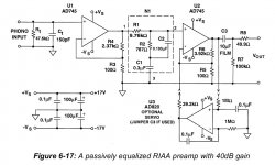
After several dissapointments with the VSPS (great sound but a noncureable noise from hell) i decided that its time for my own first phono pre circuit. After 5 days of reading and simulation I came up with a two stage opamp circuit with about 40db total gain and uses passive equalization between the gain stages, another day later i found nearly exactly the same circuit in Walt Jungs Analog Devices op amp bible (the first real book on electronics i am reading and its great, i would reconmend it to everyone who wants to get in hobby electronics). I have attached a picture of the schematic below.
Before i start with the PCB design (this time i will have them professionally made) and part sourcing i have some basic questions, maybe you can help me find some answers.
1. Has anyone ever build this circuit and can share his experiences?
2. I will make a 2 layer board... ground plane or star ground? I read the chapter on grounding but remember that i read somewhere else that its the best for audio equipment to use star ground and a shielded case.
3. The resistors : Vishay CMF-55-143 ... or cheap metal films with a worse TK and accuracy but handmatched to theoretical values of reverse RIAA equilization?
3. The caps : Vishay MKP1837 0.1uF for nearly everything, handmatched selected MKP1837 for the reverse RIAA. The other option for the network: 10nF silver mica 0.3% reference capacitors + one 3nf mkp or mp and adjusted network resistors? I am afraid of mixing different cap types. Panasonic FC for the electrolytics in the PS.
4. The Opamps : AD797 since the suggested AD745 in DIP isnt available anymore. I can solder SMD, but through hole is still easier to manage especially from a desoldering point of view
5. The circuit has no bandwith limiting capacitors, i simulated it with several values for a limiting frequency from 100kHz-200kHz but the Riaa response always got pretty worse (about 0.15dB), should i implement them anyway for safety reasons?
6.The same as above for input and output highpass/lowpass filters + I dont know how the input impedance will change with an RC Network on the In / Outputs.
7. My first LC Meter ... i know you get a tool in equal in quality to the money you spend... but will an el cheapo 15 Euro LC Meter of the bay do the trick for my first "yes wife, i will measure this bag of capacitors for another 3 hours to find the best pairs" evening?
8. Is there anything i overlooked?
The power supply will be the LC Audio low noise regulator, i have already built this one on breadboard and pcb and its working fine (but i dont own an oscilloscope so ... i cant really judge on the noise supression), maybe i will built another one and go complete dual mono with two seperate transformers, but thats something i can think about when the amp is up and running.
Thanks for all your help.
I try to make a long story short. After years of very basic hobby electronics i have reached the point where i want to fully understand circuits and develop my own too, until now i have just rebuild schematics.
I use spice simulation to learn how things work, i helped to finally understand U=RI
After several dissapointments with the VSPS (great sound but a noncureable noise from hell) i decided that its time for my own first phono pre circuit. After 5 days of reading and simulation I came up with a two stage opamp circuit with about 40db total gain and uses passive equalization between the gain stages, another day later i found nearly exactly the same circuit in Walt Jungs Analog Devices op amp bible (the first real book on electronics i am reading and its great, i would reconmend it to everyone who wants to get in hobby electronics). I have attached a picture of the schematic below.
Before i start with the PCB design (this time i will have them professionally made) and part sourcing i have some basic questions, maybe you can help me find some answers.
1. Has anyone ever build this circuit and can share his experiences?
2. I will make a 2 layer board... ground plane or star ground? I read the chapter on grounding but remember that i read somewhere else that its the best for audio equipment to use star ground and a shielded case.
3. The resistors : Vishay CMF-55-143 ... or cheap metal films with a worse TK and accuracy but handmatched to theoretical values of reverse RIAA equilization?
3. The caps : Vishay MKP1837 0.1uF for nearly everything, handmatched selected MKP1837 for the reverse RIAA. The other option for the network: 10nF silver mica 0.3% reference capacitors + one 3nf mkp or mp and adjusted network resistors? I am afraid of mixing different cap types. Panasonic FC for the electrolytics in the PS.
4. The Opamps : AD797 since the suggested AD745 in DIP isnt available anymore. I can solder SMD, but through hole is still easier to manage especially from a desoldering point of view
5. The circuit has no bandwith limiting capacitors, i simulated it with several values for a limiting frequency from 100kHz-200kHz but the Riaa response always got pretty worse (about 0.15dB), should i implement them anyway for safety reasons?
6.The same as above for input and output highpass/lowpass filters + I dont know how the input impedance will change with an RC Network on the In / Outputs.
7. My first LC Meter ... i know you get a tool in equal in quality to the money you spend... but will an el cheapo 15 Euro LC Meter of the bay do the trick for my first "yes wife, i will measure this bag of capacitors for another 3 hours to find the best pairs" evening?
8. Is there anything i overlooked?
The power supply will be the LC Audio low noise regulator, i have already built this one on breadboard and pcb and its working fine (but i dont own an oscilloscope so ... i cant really judge on the noise supression), maybe i will built another one and go complete dual mono with two seperate transformers, but thats something i can think about when the amp is up and running.
Thanks for all your help.
Attachments
You should have a look at the Nation Semiconductor data sheet for the LME49710 opamp. One of their applications is very similar. They also have an app note with other circuits you should read. I haven't built that particular circuit, but am very pleased with the LME49710 in my preamp.
I'd never go for a PCB on a preamp without breadboarding it on perf board first. Even though it won't be optimal, you'll learn things about grounding, bypassing and routing that you can apply to the PCB. This circuit is so simple there's no reason not to do so. If you can't get near zero hum and noise with perf board, you're not ready to do a PCB. Though the planes and such will help, they'd just be patching over a fundamentally flawed layout.
Have you read the Hagerman (sp?) paper on RIAA turnover points and inverse networks?
Have a look at this :
http://www.geocities.com/rjm003.geo/rjmaudio/diy_pho2.html
I built something similar 6 year ago (my first DIY project), with 80dB gain (for MC), changed almost everything, including resistor and capacitor values, opamps (AD797 + OPA637), battery driven, etc.
Am still using it today, but a discrete opamp version is in the making.
http://www.diyaudio.com/forums/showthread.php?postid=1488702#post1488702
THEL in Germany also had something similar years ago (VP-2000, around year 2002).
http://www.thel-audioworld.de/test/test.htm#VP2000
Patrick
Thanks for the infos,
i guess its a basic design and there is not much that can go wrong exept for ground hum and stray capacity.
I will order the parts and build a dead bug circuit with some generic parts to check if its working and if everythings fine i will have the pcbs made and use close matched parts.
I found some LME49721 in my free samples box i guess i will use these for the first experiments, specs look quite good.
i guess its a basic design and there is not much that can go wrong exept for ground hum and stray capacity.
I will order the parts and build a dead bug circuit with some generic parts to check if its working and if everythings fine i will have the pcbs made and use close matched parts.
I found some LME49721 in my free samples box
i guess i will use these for the first experiments, specs look quite good.The LC-Audio DC Reg is a dual tracking power supply ... noise rejection is about 90 DB, i think i am on the safe side with it.
I have build one on a selfdesigned PCB for my vsps and its workng fine so far ... but for the final project i will use one or two on a professionally manufactured pcb.
I have build one on a selfdesigned PCB for my vsps and its workng fine so far
... but for the final project i will use one or two on a professionally manufactured pcb.Hi Razorblade,
you wrote:
5. The circuit has no bandwith limiting capacitors, i simulated it with several values for a limiting frequency from 100kHz-200kHz but the Riaa response always got pretty worse (about 0.15dB), should i implement them anyway for safety reasons?
Why do want to add frequency limiting capacitors? The RIAA itself is frequency limiting.
What is important in my opinion is to match the RIAA components for the left and the right channel as close as possible.
Here the link to a very interesting article.
http://www.vacuumstate.com/fileupload/SP_15_Article.pdf
Cheers
KlausB
Maybe you can get some samples of the LME49713 -- a very low noise CFB opamp.
Wow, thats one promising looking Op-Amp ... my main problem with samples from Analog is : My email acc registered for sample ordering is down, and i cant login because i forgot my password and every new pw i request is sent to my broken down email account
Good point, i thought about that. In the original circuit there a no frequency limiting caps, leaving them out will definately improve riaa performanc, but at least the first gain stage is not riaa filtered and i am afraid of op amp oscillation. I have no scope to check if things go right so i have to trust my ears and pray for the best.Why do want to add frequency limiting capacitors? The RIAA itself is frequency limiting.
Thanks for all your help and suggestions, since this is my first project i really started from scratch every help is very welcome.
one big problem i have : how do i calculate or simulate the load of an riaa network? When i use the original riaa values of the vsps as a passive network following a simulated Ne5532 gain stage with 23dB fed by a 1khz sin wave the output is everything but a sine wave, i guess this has to do with the load but i havn't figured it out yet.
KlausB said:
Here the link to a very interesting article.
http://www.vacuumstate.com/fileupload/SP_15_Article.pdf
And here a link putting that article in another perspective:
http://www.stereophile.com/features/cut_and_thrust_riaa_lp_equalization/
Not mentioning what I wrote years ago:
http://www.tnt-audio.com/ampli/aqvox_phono2ci_part2_e.html
Hi all,
Could someone give me a hint on the quality of the usual cheapo LC meters, i want to order all the parts tomorrow. I know you get as much quality as you pay but will a cheapo lc meter be enough for the first projects and matching of the caps?
About the fourth pole: When there is nothing past 50Khz on the record, my amp cuts of at a level of ... hmmm lets say 30khz (ultra optimistic estimation)and my ears at 22Khz ... well, i dont understand whats the point of implementing the 4. pole no matter how much i read about it.
Razorblade said:
About the fourth pole: When there is nothing past 50Khz on the record, my amp cuts of at a level of ... hmmm lets say 30khz (ultra optimistic estimation)and my ears at 22Khz ... well, i dont understand whats the point of implementing the 4. pole no matter how much i read about it.
It may be hurtful to your dog's ears/
Lots of LC bridge meter schematics on the web.
some years ago, i built and used this one and been pretty happy with it. before being laid off, i had a chance to compare it with a nice (i.e. expensive, well maintained and calibrated ) hp analyzer and was not disappointed. it also has a handy delta function that is great for matching caps.
mlloyd1
) hp analyzer and was not disappointed. it also has a handy delta function that is great for matching caps.mlloyd1
Razorblade said:... Could someone give me a hint on the quality of the usual cheapo LC meters ...
Since i am running on a very tight budget i cant afford any kind of LC meter at the moment so i decided to go with the 0.3% tolerance silver micas, the values of the schematic above are changed to 10.3nF, 30nf for the caps and 97.6k and 7.87k for the resisors. Load is a little higher but still everything simulates fines, does anyone see a problem with this little change (exept for higher resistor noise) ?
Since i cant afford the equipment to handmatch all the parts i will pay the extra price to get the parts with better tolerances.
But i have another big problem: My AC main is fluctuating like hell, when i plug in my cheapo multimeter in the ac outlet i get a reading of 228V-230V jumping up and down at random. When i exhange the probes in the holes of the AC outlet i get a stable reading of 230V, the same with my LC-Audio low noise reg, when i plug it into to the main outlet i get a DC of 11.8 to 12.1 jumping up an down, when i turn the acplug of the regulator by 180 degress its suddenly stable and when i connect the GND of the regulator to the mains safety GND (Green/Yellow cable here in germany) its stable no matter how the mains plug of the regulator is connected to the main outlet, does anyone have a hint why this could be and what to do against it?
- Status
- This old topic is closed. If you want to reopen this topic, contact a moderator using the "Report Post" button.
- Home
- Source & Line
- Analogue Source
- A passively equalized OpAmp RIAA preamp