I have a parametric EQ after a preamp and I need to bypass its effect gradually, in such a way that I can control how much of the source line is affected by the EQ and how much runs directly to the output unaffected.
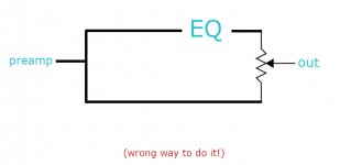
I tried the most basic workaround (no intention to offend anybody): a 10K pot to the EQ output (pot1), the source line (pot3) and the mixed output (wiper), like in the drawing below. It didn't work, lines attenuate as they mix and only in the extremes, when resistance is 0, gain is preserved.
I found some diagrams in the net on how to mix lines, some passive using only resistors and others including an opamp.
ie1. Passive balance: https://farm8.staticflickr.com/7282/9741546275_a7b5d04df7_o.gif
ie2. Active balance: http://www.geofex.com/Article_Folders/panner.pdf
ie3.: Active mixer: https://sound-au.com/articles/audmix-f3.gif
I'm up for an active circuit if necessary but I don't know which schematic is appropriate for me. These diagrams I found are for mixing different sources, like for L/R balancing or sum mixing, whereas I need to mix back the same source split. I ignore if the same principle applies.
Attachments
I don't think I have seen this implemented before - but I may have overlooked something.
It may be a little bit challenging, what you want to achieve.
The problem is that you are mixing the signal with ifself - but phase shifted.
Not knowing the details of your EQ, if may very well exhibit a phase shift of 180 degrees at one or more some frequencies (depending on EQ adjustment and complexity)
In general terms I would then expect that a 50/50 mix would actually cancel out the sound at those frequencies - probably not what you wanted.
I think you may have to consider using the EQ itself (by adjusting the level of increase/decrease in each filter section).
Cheers,
Martin
Thank you for taking the time to answer Martin. I had no idea that this was something a bit 'sui generis', no wonder why I couldn't find the keywords to research it.
For simplicity I've been trying to do it just with a few RC filters. But the actual EQ I was intending to use is the one attached, which I am building at the moment.
The general filter mix is a very useful feature that I've seen in some DAW. It allows to set a curve or set of parameters and attenuate them temporarily without loosing them. Be it to compare, do some real time production equalisation, or mild down a complex curve that has been designed in dramatic fashion for the sake of precision (ie. noise cancelling plus voice boost).
Anyways, it is very good for me to know that this is not as simple as I thought in analog! Not even close to it.
Regards,
Domingo
Attachments
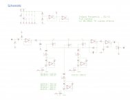
So it is a gyrator based EQ (each of the filter sections emulating a series resonant).
This is not the most used toplogy for a parametric EQ But it should work.
Beware though that the Q adjustment is a little bit overrated🙂:
The issue is that the Q is determined by the combination of the Q-potentiometer and the gain-potentiometer.
I am actually not particulary fond of this EQ topology because the filter sections also have a tendency to have a significant interaction, which in your case with a parametric version may be totally unpredictable.
As you already know of Rod Elliots site, I can recommend you to look up the "Constant Q graphical equalizer" - project 75.
Cheers,
Martin
Thanks again for your answer and suggestion Martin.
Unfortunately I need control over Q. I can understand that for many applications this is not necessary, especially for room equalisation or even tone boost. I've seen people calling parametric EQ some gear for cars that don't even have bandwidth control... :s Which makes me think there is a whole marketing or buzz around it. But I really need it and use it because I produce soundtracks. Sometimes I have to tweak a wide band just for tone or colouring in a precise Fq., sometimes to attenuate a Q5 notch in the highs, etc.
I was aware that in a Gyrator design Q changes with frequency. I've been ready to compensate that manually (ie. lowering the Q pot while frequency goes down should do it, in my mind). Also calculated my coefficients to control the ranges I usually work. But that Q also depends on gain is completely new to me! What a wild design this will be.... PCBs are on the way so I might build it anyways, but ready for the worst and hopefully it will serve somehow.
PD.: I read in Elliots' site that for proper bandwidth control state variable filters are the way to go, but couldn't find a relatively simple design to build.
Regards,
Domingo
Yes, there are the situations where control over the Q is needed.
The Q is dependend on the gyrator itself and the series resistance.
The series resistance is not only the Q-potentiometer, but also the resistance as seen "into" the gain-potentiometer.
Your Q-potentimeter is quite large - so at low Q's (maximum resistance of the Q-potentiometer) the gain potentiometer will not change the Q that much.
But at high Q's (Q-potentiometer set to minimum) the Q will change quite a bit with gain.
The result is that low gain settings are more visible (you can see the position of the gain potentiometer) than audible - so to speak.
Whereas using a filter section close to maximum or minimum gain calls for clearly audible (tonal) changes with small changes in the gain potentiometer.
The difference becomes very clear if you have the possibility to compare with a "Constant Q equalizer" - with this small changes of the gain potentiometer are audible over the whole gain interval.
My comment about the interaction between filters you can test when you have build the EQ (or do this with a circuit simulator):
Adjust the three filters to have their peaks close togther - for example one octave between each (say 200, 400 and 800Hz) - for example with a Q of around 2
Then set the gain of the high and low filters to maximum and the middle filter to minimum gain and see/hear what happens.
What you can expect to see (spoiler, I know) is that the middle frequency is not dampened at all, but stronger than the two adjacent peaks.
Another way of putting this: be very aware that the potentiometer positions will in some cases not be representative for what the EQ actually is doing.
I know this is a long'ish post - what I trying to communicate is that this rather simple analog EQ design will be able to manipulate your sound, but do not expect the sound processing to be as aligned to the potentiometer positions as you may expect from a digital sound processor.
Cheers,
Martin
I appreciate a lot your explanation Martin. I've been prepared to not expect from the circuit the same as digital processors, but inevitably that's my reference and it's good for me to be prepared. The spoiler felt like 'auch!', such a strange behaviour shall I expect... but at least I'll know that I didn't build something wrong when I test it.
I'll try to post here my comments in some time when it's built. Perhaps before giving it away to some guitar player friends and take it as a warm up for a next better EQ. Unless I manage to tame the beast... who knows!
Best regards,
Domingo
I'll try to post here my comments in some time when it's built. Perhaps before giving it away to some guitar player friends and take it as a warm up for a next better EQ. Unless I manage to tame the beast... who knows!
Best regards,
Domingo
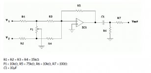
Please find a design I did some years ago and it is the same as your example. I never built it but simulation is OK under PSpice:
Mixer1 : Schematic
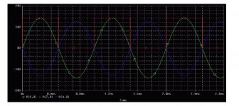
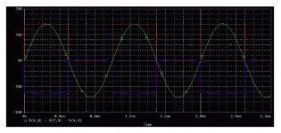
To test the design under Spice, I used the following method:
V1 is a square signal
V2 is a sinus signal
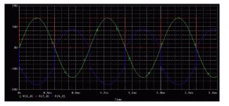
When pot is V1 side, the output is a square signal, when pot is V2 side, the output is a sinus signal and when pot is 50%, you have an adder (the AOP is wired as adder in the schematic).
Mixer 2 to 4 is the simulation results (blue curve is the output).
You could easily simulate whole circuit (with your EQ) under Tina-TI 😉
Mixer1 : Schematic
To test the design under Spice, I used the following method:
V1 is a square signal
V2 is a sinus signal
When pot is V1 side, the output is a square signal, when pot is V2 side, the output is a sinus signal and when pot is 50%, you have an adder (the AOP is wired as adder in the schematic).
Mixer 2 to 4 is the simulation results (blue curve is the output).
You could easily simulate whole circuit (with your EQ) under Tina-TI 😉
Attachments
Yes, there are the situations where control over the Q is needed.
The Q is dependend on the gyrator itself and the series resistance.
The series resistance is not only the Q-potentiometer, but also the resistance as seen "into" the gain-potentiometer.
Your Q-potentimeter is quite large - so at low Q's (maximum resistance of the Q-potentiometer) the gain potentiometer will not change the Q that much.
But at high Q's (Q-potentiometer set to minimum) the Q will change quite a bit with gain.
The result is that low gain settings are more visible (you can see the position of the gain potentiometer) than audible - so to speak.
Whereas using a filter section close to maximum or minimum gain calls for clearly audible (tonal) changes with small changes in the gain potentiometer.
The difference becomes very clear if you have the possibility to compare with a "Constant Q equalizer" - with this small changes of the gain potentiometer are audible over the whole gain interval.
My comment about the interaction between filters you can test when you have build the EQ (or do this with a circuit simulator):
Adjust the three filters to have their peaks close togther - for example one octave between each (say 200, 400 and 800Hz) - for example with a Q of around 2
Then set the gain of the high and low filters to maximum and the middle filter to minimum gain and see/hear what happens.
What you can expect to see (spoiler, I know) is that the middle frequency is not dampened at all, but stronger than the two adjacent peaks.
Another way of putting this: be very aware that the potentiometer positions will in some cases not be representative for what the EQ actually is doing.
I know this is a long'ish post - what I trying to communicate is that this rather simple analog EQ design will be able to manipulate your sound, but do not expect the sound processing to be as aligned to the potentiometer positions as you may expect from a digital sound processor.
Cheers,
Martin
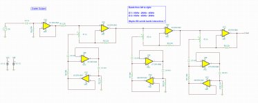
Maybe to avoid interaction idea will be to to separate each band with a dedicated AOP so for each pot/each band an AOP then for the next band add after this another pot + AOP and so on ? maybe seprate bands (I mean, for example for a 3 band EQ, instead of band 1 with aop 1 then band 2 in serie after with AOP 2 then band 3 in series after with AOP3 , inverse band 2 & 3 so in series, Band 1, Band 3 then Band 2 ??? ).
Sorry difficult to explain with words (and my bad english) so see picture 😉
The scm is just a copy of same band. I have to recalulate the values to have 3 differents bands 😉
I plan to use this design (only one band for a presence control in my future guitar amp so fc = 3.5kHz with values in SCM).
Attachments
...a 10K pot to the EQ output (pot1), the source line (pot3) and the mixed output (wiper), like in the drawing below. It didn't work, lines attenuate as they mix and only in the extremes, when resistance is 0, gain is preserved.....
If the load on the pot wiper is infinite (and both paths are unity gain*), gain is preserved for all settings of the pot.
(*) An EQ is obviously not unity gain at all frequencies. I assume you know what you really want. (My impression is that mixing-in a direct signal spoils the Q of the EQ.)
Please find a design I did some years ago and it is the same as your example. I never built it but simulation is OK under PSpice:
Mixer1 : Schematic
To test the design under Spice, I used the following method:
V1 is a square signal
V2 is a sinus signal
When pot is V1 side, the output is a square signal, when pot is V2 side, the output is a sinus signal and when pot is 50%, you have an adder (the AOP is wired as adder in the schematic).
Mixer 2 to 4 is the simulation results (blue curve is the output).
You could easily simulate whole circuit (with your EQ) under Tina-TI 😉
This is one of the circuits Domingo linked to in the first mail.
Try to apply a sine with same frequency on both inputs - but phase shifted as would happen with an analog EQ.
Then you depending on setting of the mixer and amount of phase shift can experience that the output is reduced significantly.
Cheers,
Martin
Last edited:
Maybe to avoid interaction idea will be to to separate each band with a dedicated AOP so for each pot/each band an AOP then for the next band add after this another pot + AOP and so on ? maybe seprate bands (I mean, for example for a 3 band EQ, instead of band 1 with aop 1 then band 2 in serie after with AOP 2 then band 3 in series after with AOP3 , inverse band 2 & 3 so in series, Band 1, Band 3 then Band 2 ??? ).
Sorry difficult to explain with words (and my bad english) so see picture 😉
The scm is just a copy of same band. I have to recalulate the values to have 3 differents bands 😉
I plan to use this design (only one band for a presence control in my future guitar amp so fc = 3.5kHz with values in SCM).
Splitting up the filters as shown in your diagram will work for the interaction - at least it did when I some time ago simulated it😉
There might be issues with an increased noise level due to the multiple sections in series, but that may not be an issue depending of signal level and components used.
Cheers,
Martin
(*) An EQ is obviously not unity gain at all frequencies. I assume you know what you really want. (My impression is that mixing-in a direct signal spoils the Q of the EQ.)
I'm sorry for answering late, "life was calling" as they say.
Few days ago I received the boards for the infamous Gyrator EQ. They are so tiny that I feel excited about having it done and test it, but it may take a while until I receive all caps and pots. My idea is to "sandwich" them and use dual pots to have it stereo and portable, to use with a mic preamp.
The idea of mixing in and out the source with the EQ is to have a reference and find precise blending points according to different circumstances. I know what I want, but I don't know if possible/how. Since gain might be different maybe this will be all silly, buy maybe still usable if I had the chance to even try.
"If the load on the pot wiper is infinite (and both paths are unity gain*), gain is preserved for all settings of the pot. "
Are you suggesting that I'm having a problem with impedance @PRR;6660069? So far I tried with a simple passive RC Low/High filter so gain was almost the same, but still the pot didn't mix the "duplicated" signal without attenuating dramatically towards the midpoint. The output was connected to the line in of a small field recorder (Zoom H1).
@Kartapus: I appreciate very much your generous sharing of diagrams . I'll experiment with the mixer schematic anyways once I get this done I think. At least the OPamp might do some magic. Your EQ seems very promising also but as mentioned I need control over Q and Frequencies and yours seem to be only for variable gain :/
Cheers!
Attachments

- Home
- Source & Line
- Analog Line Level
- EQ/Filter gradual bypass with potentiometer