Hi,
I'm waiting for my LM3886 power amp PCBs to come back from China so have decided to turn my attention to designing a "simple" preamp that can switch a few single-ended inputs and provide a digitally controlled volume. The idea is that it will drive the LM3886 power amp, or anything else I build in the future; I also want a line-level subwoofer-out for my REL Quake.
I like the look of the PGA23xx series chips for the volume control, and will probably go with either the 2310 or 2320 as they can use +/-12v rails (the only difference I can see is the THD values are slightly better on the 2320, and the 2310 is available in DIP).
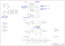
Attached is the schematic. It's a work-in-progress, as I have some questions:
1) Are the buffers pre-and-post PGA required? I've not found a consensus about this on these forums, so I've included buffers in the schematic for now.
2) Is it worth adding some additional gain, and if so where is best - before or after the PGA? I', thinking it's probably not required as the PGA itself can go up to 31.5dB.
3) Should I be including filters before the PGA? There's a 2.2uF coupling cap and a low-pass filter for filtering out RF, but I also have these in the power amp circuits. The PGA datasheet doesn't mention anything about using a DC coupling cap at the inputs.
The front-end will be driven by a microcontroller, possibly an Arduino, probably an ESP32, as I can use its built-in wi-fi to drive a phone app or web app to remote control the input, volume, balance, etc. Physical controls will be a rotary encoder and some push buttons for input selection. I'm not too concerned with this at the moment because I'm a programmer so can get things like that working quite quickly. The electronics side of things is relatively new to me, and I'm learning as I go. The power for the digital and relays will probably be a 12v switching supply with a 5v regulator for the microcontroller and the digital side of the PGA; analog power will come from a regulated linear supply that I'll build myself.
Any feedback or suggestions greatly appreciated.
Thanks, Christian
I'm waiting for my LM3886 power amp PCBs to come back from China so have decided to turn my attention to designing a "simple" preamp that can switch a few single-ended inputs and provide a digitally controlled volume. The idea is that it will drive the LM3886 power amp, or anything else I build in the future; I also want a line-level subwoofer-out for my REL Quake.
I like the look of the PGA23xx series chips for the volume control, and will probably go with either the 2310 or 2320 as they can use +/-12v rails (the only difference I can see is the THD values are slightly better on the 2320, and the 2310 is available in DIP).
Attached is the schematic. It's a work-in-progress, as I have some questions:
1) Are the buffers pre-and-post PGA required? I've not found a consensus about this on these forums, so I've included buffers in the schematic for now.
2) Is it worth adding some additional gain, and if so where is best - before or after the PGA? I', thinking it's probably not required as the PGA itself can go up to 31.5dB.
3) Should I be including filters before the PGA? There's a 2.2uF coupling cap and a low-pass filter for filtering out RF, but I also have these in the power amp circuits. The PGA datasheet doesn't mention anything about using a DC coupling cap at the inputs.
The front-end will be driven by a microcontroller, possibly an Arduino, probably an ESP32, as I can use its built-in wi-fi to drive a phone app or web app to remote control the input, volume, balance, etc. Physical controls will be a rotary encoder and some push buttons for input selection. I'm not too concerned with this at the moment because I'm a programmer so can get things like that working quite quickly. The electronics side of things is relatively new to me, and I'm learning as I go. The power for the digital and relays will probably be a 12v switching supply with a 5v regulator for the microcontroller and the digital side of the PGA; analog power will come from a regulated linear supply that I'll build myself.
Any feedback or suggestions greatly appreciated.
Thanks, Christian
Attachments
I use a buffer on the input to PGA per datasheet. No buffer on output. Watch out for ground loops if you connect USB to arduino while testing. Can make awful noise and fry PGA.
You might want to be careful of noise on coil ckt of relays. Can couple to signal flowing through contacts.
You have a great idea. From experience it works very well.
You might want to be careful of noise on coil ckt of relays. Can couple to signal flowing through contacts.
You have a great idea. From experience it works very well.
I have never experienced any reason to have input buffers on the PGA3210 and I think that most reported issues are with high impedance signal sources.
But I have an SE to balanced converter as an optional feature at the output.
Most, if not all commercial sources (DAC:s...) have an output capacitor.
A note, I use a small resistor in the range 200 ohm in line with the input and capacitor ~50-100 pF to ground directly at the connector to kill any RF noise that can enter the system (i see that they are in you schematics but further away from the connector).
That, and careful done ground plane and decoupling of the PGA2310 really is enough.
Thank you for your responses.
As I said, there's no consensus on the buffers")
Cheers, Christian
As I said, there's no consensus on the buffers
I was thinking about this, possibly adding a snubber RC network to each coil. Hopefully the switching sequence (mute PGA, switch off current source relay, switch on chosen source relay, unmute PGA), each step with a 20ms-or-so delay will make switching silent. I'll make use of the PGA's zero-crossing detection. Also, because the relay coils are only energised during switching (they're dual core latching types) there's no current passing through them normally.rkondra said:You might want to be careful of noise on coil ckt of relays. Can couple to signal flowing through contacts.
That's something I was considering for the future. My power amps are only single ended at the moment but I was looking at balanced inputs (therefore requiring balanced outputs on the preamp) for the next iteration.strongbow60 said:But I have an SE to balanced converter as an optional feature at the output.
Cheers, Christian
There is no consensus on input buffer iff you either a) do not believe the manufacturer's data sheet or b) dont care to get as much performance as you can. Page 10 of data sheet:
"For optimal performance, drive the PGA2311 with a low source impedance. A source impedance of 600 Ω or less
is recommended. Source impedances up to 2 kΩ cause minimal degradation of THD+N; see Figure 8 for more
details."
"For optimal performance, drive the PGA2311 with a low source impedance. A source impedance of 600 Ω or less
is recommended. Source impedances up to 2 kΩ cause minimal degradation of THD+N; see Figure 8 for more
details."
- Status
- This old topic is closed. If you want to reopen this topic, contact a moderator using the "Report Post" button.