Hi all
I know that this is not simple argument and not all agree about this topic but I'm not able to progress on my project.
I'm designing a preamp to adapt my dac output voltage (3V peak) to my ampli input (800mV) and introduce a volume controller.
I started from the Bruno Putzeys' article
https://www.hypex.nl/img/upload/doc/an_wp/WP_The_G_word.pdf
and from a through hole version realized by @alexcp
https://www.diyaudio.com/forums/analog-line-level/325268-balanced-volume-controller-line-stage.html
Respect to the second one I just added some bypass/decoupling caps near each opamp.
On the same board I would also add the power section and a relè for soft start.
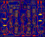
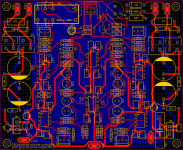
Both projects use a solid ground plane, so I realized my PCB putting a ground plane on the bottom layer.
I noted that on the Bruno's original PCB he avoided to put the ground plane under the power filter caps. This is (as I understood) to avoid that caps charging current create noise into audio section.
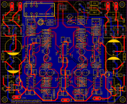
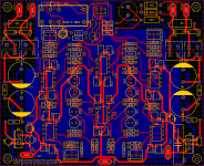
So I realized another version of my PCB in which I reduced the ground plane area and connected it in a single point to the common rail of power section (please note that the power section is splitted in 2 parts, negative voltage on the left and positive on the right side).
Now I have some doubts about both results because (for routing reson) I have some power rails on the bottom layer, horizontally, and this seems to me like a break in the ground plane.
Even if I read a lot of articles/posts/comments I'm finally not able to solve my doubts.
1. Is my first version of PCB ok?
2. Is my second version better than first one?
3. Am I right about ground plane break? Do I need to do something else?
I know that this is not simple argument and not all agree about this topic but I'm not able to progress on my project.
I'm designing a preamp to adapt my dac output voltage (3V peak) to my ampli input (800mV) and introduce a volume controller.
I started from the Bruno Putzeys' article
https://www.hypex.nl/img/upload/doc/an_wp/WP_The_G_word.pdf
and from a through hole version realized by @alexcp
https://www.diyaudio.com/forums/analog-line-level/325268-balanced-volume-controller-line-stage.html
Respect to the second one I just added some bypass/decoupling caps near each opamp.
On the same board I would also add the power section and a relè for soft start.
Both projects use a solid ground plane, so I realized my PCB putting a ground plane on the bottom layer.
I noted that on the Bruno's original PCB he avoided to put the ground plane under the power filter caps. This is (as I understood) to avoid that caps charging current create noise into audio section.
So I realized another version of my PCB in which I reduced the ground plane area and connected it in a single point to the common rail of power section (please note that the power section is splitted in 2 parts, negative voltage on the left and positive on the right side).
Now I have some doubts about both results because (for routing reson) I have some power rails on the bottom layer, horizontally, and this seems to me like a break in the ground plane.
Even if I read a lot of articles/posts/comments I'm finally not able to solve my doubts.
1. Is my first version of PCB ok?
2. Is my second version better than first one?
3. Am I right about ground plane break? Do I need to do something else?
Attachments
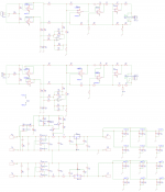
Can you post the actual board schematic?
Having excessive ground plane splits often means either that four layers are needed,
or that the component placement needs rethinking.
Having excessive ground plane splits often means either that four layers are needed,
or that the component placement needs rethinking.
Last edited:
I think the overall functional block placement on this board will be ok. Leave all the parts where they are for now.
For a start, remove all the traces from the audio circuits, and then try to route their power supply +/- connections
on the component side in the most direct manner. Then when you next add the audio circuit traces on the component side,
you can use some of the resistors as jumpers if that would be useful.
Don't forget you can swap op amps within a package if that would be more convenient. Where necessary,
the breaks in the ground plane for some of the audio circuit connections that must be on the bottom side
will be small, since these traces will be much shorter than the long power supply traces.
Last edited:
Hi all.......Do I need to do something else?
What a load of cr@p!!! I am wondering if either of my learned friends even read the first paragraph of your post. Please no disrespect but even you did not know what you wanted from the rest of your mail.
Yes you can lay a fantastic board and have an incredible schematic, but really all you need is a volume control with a few wires, zero noise, zero distortion and zero earth loops added.
And yes, you can even make a very sophisticated PCB for it if you feel the inclination while mounting it in the main amp box with only a single little hole in the face plate where the volume knob will be. The cost will be miniscule.
It does not even require any power supply, or impedance matching, there will be no ground loops and the cost that you save you can donate to me.
The problem as I see it, you need a "pre-amplifier" (with negative gain) an attenuator. There need for no anti-pop relays or anything of the like - no nothing..... Stop dreaming and approach the problem like an engineer.
One dual POT with a resistance to match the amp input "impedance" which probably would be 10K (look at the input of your amp diagram or even measure it with your DVM.)
There is most likely a resistor across input. If you read nothing on the DVM, most likely there is a series capacitor (followed by the resistor), then you may simply inspect it physically.
I realize that this might not sound as sophisticated as you anticipate, but heck you can tell your buddies anything you like. With the savings you can purchase the most expensive high-end gold-plated potentiometer, or donate it to me.
Instead of adding a lot of crap that would change your sound markedly with the additional rubbish that you intend fitting, it would be the exact opposite at full throttle the noise would be the same as now and at cut, it would reduce to nothing.
You may ask what about inputs, well even that you can simply add using a simple switch and if you really need a few relays (of course another expensive hole in the amp face plate).
Guy wake up smell the roses, it is as simple as it sounds.
Last edited:
I think the overall functional block placement on this board will be ok. Leave all the parts where they are for now.
For a start, remove all the traces from the audio circuits, and then try to route their power supply +/- connections
on the component side in the most direct manner. Then when you next add the audio circuit traces on the component side,
you can use some of the resistors as jumpers if that would be useful.
Don't forget you can swap op amps within a package if that would be more convenient. Where necessary,
the breaks in the ground plane for some of the audio circuit connections that must be on the bottom side
will be small, since these traces will be much shorter than the long power supply traces.
Ok, clear. I will try this approach as soon as possible. But do you think that I have to place the ground plane for the full bottom layer or as I did in the second version just under the audio section?
Thanks
.....
The problem as I see it, you need a "pre-amplifier" (with negative gain) an attenuator. There need for no anti-pop relays or anything of the like - no nothing..... Stop dreaming and approach the problem like an engineer.
......
You are right, I need an attenuator... but this is an hobby, not my job, I'm trying to learn with the experience... if I don't want to dream I can buy a preamp in a shop and that's it.
From my point of view this is the first step. If the result will be good I will try to go on with another project that probably make more sense for you...
Last edited:
You will learn that is a fact. You have learned something by the other two contributors . Laying PCBs and playing with simulation is a video game and you can become excellent without spending one penny. There are many EMC simulation add on package that will test your design completely and point out all the ****-ups. It will become second nature to visually inspect any work and predict its performance.There are circuit simulators that you can present a .WAV file too and you can analyse input to output in foobar or even listen to it without costing you to build it. You can design anything and when you feel like it inspect your handiwork and enjoy your creation. Although I was trained in Electronics, it was a tedious process to make something work properly and not the simplicity of audio, that is a joke, but in altimeters for bomb fuses, etc. Were a bit of hum or noise is not irritation it is a disaster. Developments that spanned 2 and three years then I can do now in a weekend. Only look at Borberly, or any of your gurus work and try to figure why it is done as it is. Ground planes are the lazy man's solution to almost everything except commercial cost. If you really want to learn something go check out Bonzai at hifisonix.com: Audio Amplifier Design join his party!
My suggestion is first do the simple mod on your amp and the mess with a sophisticated system in an attempt to beat it, this is the starting and learning point.
Very good luck my friend and all the "learners" on this forum.
I come here only occasionally these days to lurk around and see what new ideas come about, but sadly and amplifier regardless of its apparent sophistication is only a micro component in the electronic field, and turns into a little hobby for some of us not in the know.
How do you even think that an industry can be built on high-end audio. It is a complete farce and the volumes they make and the irrational hype that goes with that fetch these guys some money, while elsewhere in the electronic industry they may not even have the knowledge to get a job. Think about this. What would happen if the designers of your electronic braking system with a hundred or more components in it was hampered by a little hum? How would it affect the performance of your PC if one bit is a little delayed. DACs and ADCs have been around since the beginning and do you think that the hype around an ESSXXXX DAC was required to get the guys on the moon? Start with something simple that you want to improve and then do so, you already have the best you can do, now improve it. Don't add layers upon layers of expensive PCB because it is fashionable or seems that high-end equipment looks like that. It is made for money and bragging rights to those who has no idea. Remember signals run in the least resistive parts and closer and closer to the conductor surface from as little as 1 Hz.
Have fun guy, you will get there, copying others work is no great feat and far less satisfying that getting an extraordinary result by yourself.
Last edited:
You will learn that is a fact. You have learned something by the other two contributors . Laying PCBs and playing with simulation is a video game and you can become excellent without spending one penny. There are many EMC simulation add on package that will test your design completely and point out all the ****-ups. It will become second nature to visually inspect any work and predict its performance.There are circuit simulators that you can present a .WAV file too and you can analyse input to output in foobar or even listen to it without costing you to build it. You can design anything and when you feel like it inspect your handiwork and enjoy your creation. Although I was trained in Electronics, it was a tedious process to make something work properly and not the simplicity of audio, that is a joke, but in altimeters for bomb fuses, etc. Were a bit of hum or noise is not irritation it is a disaster. Developments that spanned 2 and three years then I can do now in a weekend. Only look at Borberly, or any of your gurus work and try to figure why it is done as it is. Ground planes are the lazy man's solution to almost everything except commercial cost. If you really want to learn something go check out Bonzai at hifisonix.com: Audio Amplifier Design join his party!
My suggestion is first attempted the simple mod on your amp that adds the least interference and then mess with more sophisticated system in an attempt to beat it, this is the starting of your learning point.
Very good luck my friend and all the "learners" on this forum.
I come here only occasionally these days to lurk around t see what new ideas come about, but sadly there is nothing in amplifiers regardless of its apparent sophistication is only a micro component in the electronic Cosmos. Mostly just a little hobby with very little science for most to spend time on, like making a coffee table. You start with no legs and find it not much useful and only after scratching your head you hang it with four strings to the ceiling, and find it too unstable, days later you turn it into a box to fix the problem, much later you save some money by replacing the box with four legs.
How do you even think that an industry can be built on high-end audio. It is a complete farce and the volumes they make and the irrational hype that goes with that fetch these guys some money, while elsewhere in the electronic industry they may not even have the knowledge to get a job. Think about this. What would happen if the designers of your electronic braking system with a hundred or more components in it was hampered by a little hum? How would it affect the performance of your PC if one bit is a little delayed. DACs and ADCs have been around since the beginning and do you think that the hype around an ESSXXXX DAC was required to get the guys on the moon? Start with something simple that you want to improve and then do so, you already have the best you can do, now improve it. Don't add layers upon layers of expensive PCB because it is fashionable or seems that high-end equipment looks like that ground planes have their specific purpose in HF. It is made for money aesthetics and bragging rights to those who has no idea.
Remember signals follow the least resistive path and closer and closer to the conductor surface with frequency from as little as 1 Hz.
Have fun guy, you will get there, copying others work is no great feat and far less satisfying that getting an extraordinary result by yourself.
You will learn that is a fact. You have learned something by the other two contributors . Laying PCBs and playing with simulation is a video game and you can become excellent without spending one penny. There are many EMC simulation add on package that will test your design completely and point out all the ****-ups. It will become second nature to visually inspect any work and predict its performance.There are circuit simulators that you can present a .WAV file too and you can analyse input to output in foobar or even listen to it without costing you to build it. You can design anything and when you feel like it inspect your handiwork and enjoy your creation. Although I was trained in Electronics, it was a tedious process to make something work properly and not the simplicity of audio, that is a joke, but in altimeters for bomb fuses, etc. Were a bit of hum or noise is not irritation it is a disaster. Developments that spanned 2 and three years then I can do now in a weekend. Only look at Borberly, or any of your gurus work and try to figure why it is done as it is. Ground planes are the lazy man's solution to almost everything except commercial cost. If you really want to learn something go check out Bonzai at hifisonix.com: Audio Amplifier Design join his party!
My suggestion is first attempted the simple mod on your amp that adds the least interference and then mess with more sophisticated system in an attempt to beat it, this is the starting of your learning point.
Very good luck my friend and all the "learners" on this forum.
I come here only occasionally these days to lurk around t see what new ideas come about, but sadly there is nothing in amplifiers regardless of its apparent sophistication is only a micro component in the electronic Cosmos. Mostly just a little hobby with very little science for most to spend time on, like making a coffee table. You start with no legs and find it not much useful and only after scratching your head you hang it with four strings to the ceiling, and find it too unstable, days later you turn it into a box to fix the problem, much later you save some money by replacing the box with four legs.
How do you even think that an industry can be built on high-end audio. It is a complete farce and the volumes they make and the irrational hype that goes with that fetch these guys some money, while elsewhere in the electronic industry they may not even have the knowledge to get a job. Think about this. What would happen if the designers of your electronic braking system with a hundred or more components in it was hampered by a little hum? How would it affect the performance of your PC if one bit is a little delayed. DACs and ADCs have been around since the beginning and do you think that the hype around an ESSXXXX DAC was required to get the guys on the moon? Start with something simple that you want to improve and then do so, you already have the best you can do, now improve it. Don't add layers upon layers of expensive PCB because it is fashionable or seems that high-end equipment looks like that ground planes have their specific purpose in HF. It is made for money aesthetics and bragging rights to those who has no idea.
Remember signals follow the least resistive path and closer and closer to the conductor surface with frequency from as little as 1 Hz.
Have fun guy, you will get there, copying others work is no great feat and far less satisfying that getting an extraordinary result by yourself.
So I would thank you for your lession...
It is clear that you are trying to help me to save time and money and it is also clear that you have a lot of experience in audio design.
So I would appreciate if for few minutes you forgot part of my first post and suppose that my schema is not an attenuator but it has positive gain.
In this case can you argument some suggestion/answer to my questions?
So I would thank you for your lession...
Lesion spells with one "s". Otherwise, you're spot on 😀
Lesion spells with one "s". Otherwise, you're spot on 😀
I created a new word... in the middle between lesson and lesion... mistery of mind...

I think the overall functional block placement on this board will be ok. Leave all the parts where they are for now.
For a start, remove all the traces from the audio circuits, and then try to route their power supply +/- connections
on the component side in the most direct manner. Then when you next add the audio circuit traces on the component side,
you can use some of the resistors as jumpers if that would be useful.
Don't forget you can swap op amps within a package if that would be more convenient. Where necessary,
the breaks in the ground plane for some of the audio circuit connections that must be on the bottom side
will be small, since these traces will be much shorter than the long power supply traces.
So I moved some component to have space for power rails.
As you can see I reduced the number of wires on the bottom layer and only in few case they are under signal wires.
Do you think that I'm on the right way?
Attachments
This is certainly better, and when to stop is your call. What is essentially a single-sided board
will always be challenging, for so many components.
will always be challenging, for so many components.
Last edited:
Lesion spells with one "s". Otherwise, you're spot on 😀
OOPS! He was offended and insulted. Guess you cannot beat them all. He probably assumed, that I meant not take note from others. Guess a lot to learn. 😕
 😱
😱HEY BUDDY, I AM TERRIBLY SORRY FOR MY COMMENT DOUBLE POSTED AND ALL!
I also improved all connections on the top to avoid to use bottom layer.
Some wires more long but that are just for mute...
Think you're getting the hang of it. Be sure to run a design check. Manual routing is best for audio,
but verify all the net connections.
Last edited:

Think you're getting the hang of it. Be sure to run a design check. Manual routing is best for audio,
but verify all the net connections.
Make no mistake moan, ggerla is not ignorant! I made that mistake. All he wanted was an opinion on his ground plane.
 The auto router obviously has EMI/RFI and every thing else under control.
Last edited:
Think you're getting the hang of it.
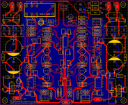
And finally, after a lot of rework, I routed all signal wires on top layer without ground plane breaks under them.
There are only 4 short wires on the bottom layer and all are under power rails.
Wdyt?
Attachments

- Home
- Source & Line
- Analog Line Level
- Preamp - ground plane and returning current