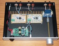
I built a small active pre amp that uses 2 different modules sharing the same power supply.
Each module when tested gives a 0mV DC offset but when both are used together the DC offset rises to 30mV in the first stage and also some odd readings in the second stage.
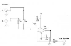
First stage is basically a ESP P88 light with LM4562 with a gain of 2 using the front and back end of this pre amp design. It has 2 outputs in parallel with one as a pre out and the other feeds a sub output via mixing resistors and NE5534 with a gain of 3. These are powered by 7812/7912 regs from a 12VAC plug pack.
I also tried a NE5532 module with one half unused and wired as per TI implementation and has the same result.
The pic shows the layout but the sub module is not wired as at the moment is has dual pre outs.
I'm a bit puzzled with this result as I've looked at sub out schematics on some commercial amps but maybe I should feed both modules from the pot and not input the second sub module from the output of the first pre amp module.
Where have I gone wrong?
Each module when tested gives a 0mV DC offset but when both are used together the DC offset rises to 30mV in the first stage and also some odd readings in the second stage.
First stage is basically a ESP P88 light with LM4562 with a gain of 2 using the front and back end of this pre amp design. It has 2 outputs in parallel with one as a pre out and the other feeds a sub output via mixing resistors and NE5534 with a gain of 3. These are powered by 7812/7912 regs from a 12VAC plug pack.
I also tried a NE5532 module with one half unused and wired as per TI implementation and has the same result.
The pic shows the layout but the sub module is not wired as at the moment is has dual pre outs.
I'm a bit puzzled with this result as I've looked at sub out schematics on some commercial amps but maybe I should feed both modules from the pot and not input the second sub module from the output of the first pre amp module.
Where have I gone wrong?
Attachments
Last edited:
Could you draw a schematic of the whole thing, with annotations about what you measure where? That could make it easier to follow than your description in words.
We really need to see a full circuit of what you have actually built and the parts used. You should apply shorting links to all inputs while testing to make sure no noise is picked up.
The NE5532 is one of the worst for DC offset if the circuit is not appropriately designed, the 4562 much less so and the TL072 has no offset issues due to it being a FET input stage.
You should also check with a scope to make sure that no high frequency instability is present, the 5534 being one that could do this if the design and layout is not correct.
I've added a schematic where the pre amp section is shown only for one channel and the other uses the same values.
Power supply runs +12.17VDC and -12.05VDC and 47-100uF caps on the rails with 100nF X7R by-pass.
Each module when run individually has 0mV DC offset.
When running LM4562 pre with NE5532 sub module I get:
LM4562 pre out -8mV, NE5532 sub out 0mV
When running LM4562 pre with NE5534 sub module I get:
LM4562 pre out -32mV, NE5534 sub out 0mV.
DC offset the same if inputs shorted or not.
I'm thinking of adding a cap at the input of the sub module prior to the mixing resistors or take the input from the pot and not the pre module.
The only measuring gear I have is a DMM. At this stage I will use the NE5534 module as a mixer elsewhere and use the NE5532 module in this pre amp.
Attachments
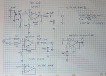
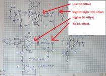
The 4562 stage as drawn should have very low DC offset as measured on the opamp output and 0 volts offset when measured at the output of the coupling cap... provided it is not connected to anything else.
The 5532 stage is the problem imo. You have DC gain of '2' with the two 10k resistors setting the gain and also you have the input coupled to ground via the 100k (+10k series resistor/s) at the output of the 4562 stage.
The 5532 has relatively high input bias currents and that current flows in the 100k and 10k input resistor and so develops a small voltage at the input pin. You then make that worse by amplifying it.
A 4562 would be a lot better than 5532 for that and a FET opamp better still.
Yes. LME49880 comes to mind.
While you are it please add a simple RC filter at the inputs to avoid the device amplifying anything way above the audio band coming in. As omitting muting seems to be in vogue these days (don't get me started 😉) I would add that too to avoid nasty power on/off effects. Preferably the non intrusive "output shorting" type with a very small telecom relay. Saves amplifiers/saves woofers/saves annoyance.
Substitute the 10 µF bipolar for a 10 µF film cap as these are quite small and cheap nowadays. Sound better too.
Last edited:
No, that stage is AC coupled on the output so has no output offset. The input offset is a fraction of a volt and not an issue for headroom.The 5532 stage is the problem imo. You have DC gain of '2' with the two 10k resistors setting the gain and also you have the input coupled to ground via the 100k (+10k series resistor/s) at the output of the 4562 stage.
The 5532 has relatively high input bias currents and that current flows in the 100k and 10k input resistor and so develops a small voltage at the input pin. You then make that worse by amplifying it.
A 4562 would be a lot better than 5532 for that and a FET opamp better still.
If there is a DC offset on any of these stages as drawn you must have a leaky coupling cap or significant resistance in some of the ground paths.
No, that stage is AC coupled on the output so has no output offset. The input offset is a fraction of a volt and not an issue for headroom.
If there is a DC offset on any of these stages as drawn you must have a leaky coupling cap or significant resistance in some of the ground paths.
True enough when looking at the output.
Oscillation can cause DC shift when looked at on a DVM, particularly if it is asymmetrical.
Attachments
Thanks for your help and wisdom.
The only FET I have is a OPA2134 so tried that in the sub module and the DC offset dropped down to 0mV. Tested and the only other thing I had to do was to ground the pot body to the pre module to remove some noise.
Not sure what and where for the RC filter but I assume it's a resistor and a small 220pF cap to ground (after the 1k). Any suggestions?
The BP caps I use are Nichicon ES and should be fine for the sub module.
I've made a note on the ground path and this build has it built via link wiring so I'm going to build another but all on the one board that has good traces for the ground.
Thank you very much again.
A 1 kOhm and 470 pF (or 2.2 kOhm and 220 pF) styroflex or other quality film cap before the volume potentiometer would be fine. If you put the RC network after the volume you would have a variable filter.
Last edited:
Thanks for your help and wisdom.
The only FET I have is a OPA2134 so tried that in the sub module and the DC offset dropped down to 0mV. ...........
Thats good 🙂 Very useful things are FET input opamps.
If low DC offset and DC precision is required while using bjt devices then the circuit has to be designed with that in mind.
First check all your sources if they have output caps (DC blocking caps). Most have those and in general you will then be having 2 in series but never mind that for this moment.
Now when you use solely JFET input opamps AND your sources are free of DC offset (a few mV is tolerable) the input cap can go, just like the output caps. It is very wise to keep an input cap at the power amplifier(s). This to avoid the power amplifiers to amplify a DC signal when something goes wrong or the servos to react to the offset of the preamp.
The best coupling cap is no cap. Best bandwidth too.
I could write a book about the lack of a standard concerning coupling caps in asymmetric audio but I won't. In general: don't be surprised to find a DC coupled source paired with a DC coupled power amplifier (HIGH risk of failure!) or a source with output capacitor coupled to a power amplifier with input capacitor 😀 In the past the latter lead to larger value caps in outputs to prevent bass roll off with Japanese audio. My own standard is to check sources and keep just 1 cap at the power amplifiers input. That makes the power amps versatile and the woofers stay happy too.
If you have sources that have to much offset DC voltage (CD players in mute are a good example) then keep the input cap but the output cap can be omitted if you use only a cap at the power amplifiers input.
Drawback of DC coupling: definitely needs a muting relay as full rail voltage may be at the outputs for a short time at power on/off.
Last edited:
No, that stage is AC coupled on the output so has no output offset. The input offset is a fraction of a volt and not an issue for headroom.
If there is a DC offset on any of these stages as drawn you must have a leaky coupling cap or significant resistance in some of the ground paths.
After the first stage's output AC coupling cap, there is a 100 kohm resistor that has to conduct half the input bias current of an NE5534 that is connected to it (but it is connected via label in the schematic, so it's easy to overlook). The thread starter measures a -32 mV offset across that 100 kohm, so that boils down to 320 nA through the 100 kohm and 640 nA total input bias current of the NE5534. The NE5534 datasheet says 500 nA typical, 1500 nA maximum.
I think Mooly's explanation matches perfectly with the measurements.
Besides changing op-amps, you can also reduce the 100 kohm to 10 kohm, connect the NE5534 stage to the other side of the AC coupling cap or try to figure out how much offset you can allow; maybe 32 mV is perfectly OK.
Last edited:
- Home
- Source & Line
- Analog Line Level
- Active pre amp DC offset increases with 2 modules used