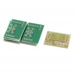
I have a potentiometer PCB that has 2 inputs... R1GL1 and R2GL2.
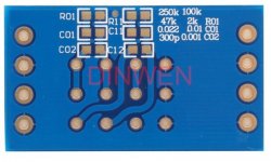
Input 1 (R1L1) is standard but looks like input 2 (R2L2) goes to a resistor at R1L1 by the top PCB marking. The question I have is what is the purpose of this resistor in series with the input? From the listing it's referred to "when using the decay resistor".
Input 1 (R1L1) is standard but looks like input 2 (R2L2) goes to a resistor at R1L1 by the top PCB marking. The question I have is what is the purpose of this resistor in series with the input? From the listing it's referred to "when using the decay resistor".
Attachments
- Status
- This old topic is closed. If you want to reopen this topic, contact a moderator using the "Report Post" button.