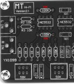
These are on eBay as YX1099 and WM-025 with the latter looking as a better design. After building the first one I found the gain so high it was overloading the input on a little Tripath amp. When used as additive equalisation, the amp would distort so subtractive equalisation was only possible.
The gain is set at 10 by the 100K resistor near the first op amp (inverting) in conjunction with the 10K input resistor. To solve my problem changing the 100K to 10K gives a gain of 1 which matches my source and amp with the volume the same as previous. As I didn't want to remove the 100K, I paralleled a 10K to give around 9K which gives gain of 0.9. I've mentioned this as there is a zillion of these things being sold and others may have the same issue.
I only used the PCB from the kit and used my own components as they are of known quality and ended up using LM4562. One thing I did add was a 100nF monolithic by-pass cap between pins 4 and 8 on each op amp under the PCB. I also run this via a 12VAC wall wart instead of a 12-0-12AC supply with a centre tap.
Hope this helps someone in the future and even though I used 10K, if more gain is required then use a higher value.
Attachments

Last edited:
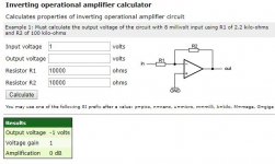
Probably have been easier to remove R2 & R3 to give you a gain of 1. Replacing the 100k with 10k gives you a gain of approximately 2.
Formulae is; 10k + 10k over 10k = 2. (20/10 = 2/1 = 2)
9k + 10k / 10k = 1.9
Formulae is; 10k + 10k over 10k = 2. (20/10 = 2/1 = 2)
9k + 10k / 10k = 1.9

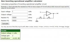
If it was non inverting then the gain would be 2 but the input R2 and R3 go to pins 2 and 6 making it inverting and hence a gain of 1.
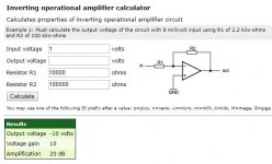
The calcs and schematic below show gain for inverting 10K, non inverting 10K and the original 100K with specified gain of 10.
The calcs and schematic below show gain for inverting 10K, non inverting 10K and the original 100K with specified gain of 10.
Attachments
An update for the record, I ended up using 15K which gives me around 3.5dB gain. For 6dB gain use 20K.
I find it's not the flat gain that's an issue it's the amount of boost and cut that's way too high. You need realistically about plus and minus 6dB of boost and cut.

- Home
- Source & Line
- Analog Line Level
- Ebay NE5532 pre amp tone control gain reduction