Hi,
This is a development of my "Active volume control with balanced output using 2 op-amps" :
Active volume control with balanced output using 2 op-amps
I wondered if I could add a quasi-floating output to this circuit which already has a balanced output. I have been considering the following quasi-floating circuits :
COHEN Graeme John "Double balanced microphone amplifier" 1984-09_AES presentation.
MARGAN Erik "Interconnects in audio" page 36, figure 7, volume 5 2013-204_Linear Audio.
PORTER Barry 1990 "Electronically balanced audio output stage" 1990-09_Wireless World.
SELF Douglas p548, figure 19.10, "Small signal audio design" second editon.
VAN DE GEVEL Marcel "Electronics audio balun" 2006-05_Electronics World and Wireless World.
The Margan's circuit uses an already balanced circuit, it was source of inspiration. In it, the common mode signal of the output is inverted by an inverting op-amp and applied to the in- of the two non-inverting op-amps which deliver the floating output signal.
My idea was that using inverting output op-amps, the common mode signal can be directly injected to the in+, saving an op-amp.
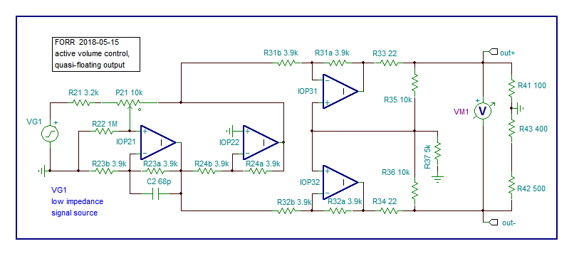
Here is the schematics. The output voltage is sensed by VM1 whcih is maintained constant whatever the ground connexion to in+, between R41 and R43, between 43 and R42, to in- or not connected at all.
.
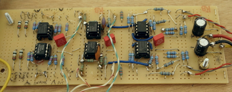
I built the circuit twice, using components from my junk box, it worked as intended.
This is a development of my "Active volume control with balanced output using 2 op-amps" :
Active volume control with balanced output using 2 op-amps
I wondered if I could add a quasi-floating output to this circuit which already has a balanced output. I have been considering the following quasi-floating circuits :
COHEN Graeme John "Double balanced microphone amplifier" 1984-09_AES presentation.
MARGAN Erik "Interconnects in audio" page 36, figure 7, volume 5 2013-204_Linear Audio.
PORTER Barry 1990 "Electronically balanced audio output stage" 1990-09_Wireless World.
SELF Douglas p548, figure 19.10, "Small signal audio design" second editon.
VAN DE GEVEL Marcel "Electronics audio balun" 2006-05_Electronics World and Wireless World.
The Margan's circuit uses an already balanced circuit, it was source of inspiration. In it, the common mode signal of the output is inverted by an inverting op-amp and applied to the in- of the two non-inverting op-amps which deliver the floating output signal.
My idea was that using inverting output op-amps, the common mode signal can be directly injected to the in+, saving an op-amp.
Here is the schematics. The output voltage is sensed by VM1 whcih is maintained constant whatever the ground connexion to in+, between R41 and R43, between 43 and R42, to in- or not connected at all.
.
I built the circuit twice, using components from my junk box, it worked as intended.
Attachments

Last edited: