Hello All,
I have an original Cyrus Power and Pre combo (the one that's 23 years old!).
Three times now I have been listening to music just fine for a couple of hours then all of a sudden the Power flashes the LED yellow. The manual says this means DC was detected at the outputs.
I have already tried going over all the joints to refresh possible dry solder. No help.
Any tips on where to go next? On the corner of the PCB there are some very hot looking (blackened PCB) regulators and bits. Maybe they need replacing but I'd have expected ICs to either work or not.
Parts that run hot are primary suspects, and yes regulators can and do fail more often than might be realised. Almost always this is down to the way they have been used rather than an inherent issue with the devices.
If you are 100% certain no dries are the cause of the issue then I would look to replacing the VAS transistor in the power amp on the grounds that it probably runs hot and is probably of a type/package/manufacturer that is known to suffer various intermittent failure modes. If you suspect the regs and they are in a part of the circuit that could affect DC offset then just change them.
If you are 100% certain no dries are the cause of the issue then I would look to replacing the VAS transistor in the power amp on the grounds that it probably runs hot and is probably of a type/package/manufacturer that is known to suffer various intermittent failure modes. If you suspect the regs and they are in a part of the circuit that could affect DC offset then just change them.
I checked the DC on the output and it does seem much higher on the left channel. I watched it get as high as 240mV. I bet it switches the amp off at 250mV.
There is one small pot per channel, but it doesn't seem to affect DC offset. There is also a bias test point and I get about 3mV on there. Here is a photo.
Any tips what I need to check or adjust?

There is one small pot per channel, but it doesn't seem to affect DC offset. There is also a bias test point and I get about 3mV on there. Here is a photo.
Any tips what I need to check or adjust?

We would really need to see a circuit diagram to be able to advise further. A DC offset that alters slightly isn't a common fault generally. Most such faults give a definite swing to one of the rails rather than a small indeterminate offset.
One possible approach could be to let the offset trip out and then very carefully use freezer spray to see if any of the small transistors respond to cooling. You can use a can of cheapo air duster (poundland) as freezer by inverting the can. You need to practice dispensing the stuff literally drop by drop. If you blast a whole area then you have no idea what you actually cooled.
One possible approach could be to let the offset trip out and then very carefully use freezer spray to see if any of the small transistors respond to cooling. You can use a can of cheapo air duster (poundland) as freezer by inverting the can. You need to practice dispensing the stuff literally drop by drop. If you blast a whole area then you have no idea what you actually cooled.
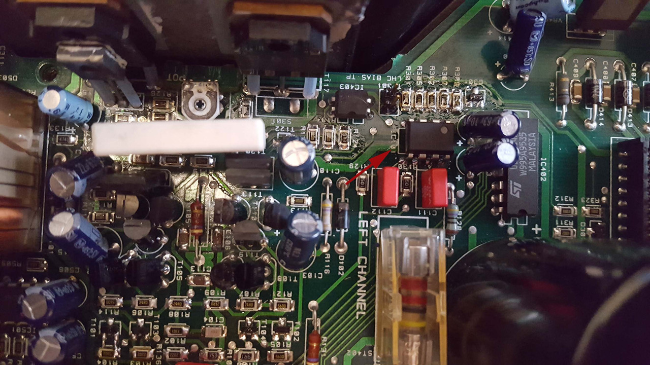
Right.. I found that dropping a bit of alcohol on T101 made the DC bias go all over the place. Blowing on it makes it reduce. I also found just poking it with a stick makes it fluctuate a little. So I was thinking I found the culprit, but actually poking T201 on the other channel also makes the DC bias vary, so I dunno.
I suppose I'll try swapping the part. It is a SOT23 with 3B on it and a Z (or sideways N) in the top left corner. Anybody able to identify this? Looks like BC856 of some kind?


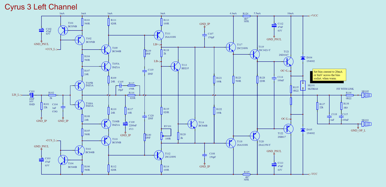
If it helps, the circuit may be similar (but not identical) to the Cyrus 3 from the same time period.

I suppose I'll try swapping the part. It is a SOT23 with 3B on it and a Z (or sideways N) in the top left corner. Anybody able to identify this? Looks like BC856 of some kind?
If it helps, the circuit may be similar (but not identical) to the Cyrus 3 from the same time period.
Hmmm... not so sure on that. Changes in bias current shouldn't trip anything. Also moisture (conductive) could be a factor when dripping ISO onto things.
Poking the board definitely shouldn't alter things to any degree. Preset resistors might be influenced a little but that all.
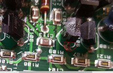
Things like this are suspect. Notice how the solder appears cracked around the joint. You need to look closely at all components to check the soldering.
Poking the board definitely shouldn't alter things to any degree. Preset resistors might be influenced a little but that all.
Things like this are suspect. Notice how the solder appears cracked around the joint. You need to look closely at all components to check the soldering.
Attachments
DC offset should not alter with any physical disturbance of the board so if you can get the offset to vary by applying pressure then that points to something physical.
I know faults like this can be difficult but you just have to keep a clear head and approach it logically. I still think freezer spray could be worthwhile. Your earlier pictures show what look to be some TO126 style transistors (like a BD131 package). Do they run hot ? and have you checked those for dries.
I know faults like this can be difficult but you just have to keep a clear head and approach it logically. I still think freezer spray could be worthwhile. Your earlier pictures show what look to be some TO126 style transistors (like a BD131 package). Do they run hot ? and have you checked those for dries.
Alright I fixed it!
I tried swapping some of the SMD transistors from left to right channels and the behaviour stayed just the same. I carried on selectively cooling parts and found a NE5532 on each channel were running too hot to touch. When I blew on it through a straw the left channel DC offset would drop immediately. Doing the same to the right hand channel and the offset stayed pretty steady.
I swapped out the original Phillips NE5532 for new National NE5532 and not only do they run FAR cooler, the offset on both channels is now at a steady 3mV.
It looks like the parts have something to do with bias as they are next to the test point and some SMD resistors.
Anybody know why the Philips parts were running so hot? Is it a differnce between the old and new designs or some affect of ageing (resistance in bond wires?)?
HOWEVER, I broke the bias pot on the left channel with hot air and I don't think it's set correctly on the right channel either. I asked Cyrus what I should set the bias at and they absolutely refuse to tell me. What the hell?! It's a 23-year old amp that I already repaired. All I need is a figure like '8mV', but they tell me to take it to an 'authorised service provider'. They are as bad as Apple and Tesla. Last time I recommend Cyrus to anybody.
Anyway I found a proper schematic for the Cyrus 3 which although different in some ways does use the same output devices and main resistor value (0.22R). The schematic says set the test point at 8mV so I'll do the same here.
Last edited:
Well that's good ") Well done.
Well done.
The 5532 may be some kind of servo... although it is an unlikely device to use for that role, I have seen it before.
Just some random failure I guess although it would be worth checking the supplies to it, and also checking the regulators that feed the chip.
Well done.The 5532 may be some kind of servo... although it is an unlikely device to use for that role, I have seen it before.
Just some random failure I guess although it would be worth checking the supplies to it, and also checking the regulators that feed the chip.
- Status
- This old topic is closed. If you want to reopen this topic, contact a moderator using the "Report Post" button.
- Home
- Source & Line
- Analog Line Level
- Cyrus Power Amp Flashes Yellow