No, I don't 🙂 It is kinda difficult to debug your board by the seat of one's pants. You need to do some systematic analysis in order to isolate and identify the problem. For example:
- Check is the noise is coming from your signal source
- Check if your power amplifier makes the noise by itself
- Compare one channel with the other
- Check your power supply voltage and current
- Check DC and AC voltages, compare if the two channels have close readings in the same points
- Check if the power supply is clean (no noise on power rails)
- Check the circuit with the scope, stage by stage, and see where the problem appears first
- Etc.
I spent a lot of hours to do several test and combination.
The power line of the preampli seems clean.
If I connect the preampli to the ampli but without source into preampli the output is clean.
So I startet to analyze the source. The source is a raspberry + dac.
The DAC is this one
SA9227 + PCM5102A 32BIT/384KHZ USB DAC/hifi decoder asincrono per Android | eBay
I tryed to power the raspberry with a battery instead that using the power suplly, but the problem is still present. Thean I tryed to connect the DAC directly to the battery instead that to the raspberry USB and in this way the problem disappear.
So it seems that the USB power from raspberry goes into the signal.
But the question is, why this doesn't happen when I connect the DAC directly to the ampli?
So finally I found and isolated all problems.
What I heared during last days is a SUM of 2 effects.
1. USB interference. It is due to USB connection between DAC and source. It sounds like a "prprprpr". As possible solution for this I can use powerbank to power the raspberry. I don't like this so I will try other solutions, but for now it is a chance.
2. 50Hz hum from preampli. It sounds as classical power hum. I tried to power the preampli with batteries and the problem disappers. How can I solve this? I'm not able to understand why I have this problem.
Is the hum coming from both channels? The AC in connectors are pretty close to the left channel output.
Is the hum coming from both channels? The AC in connectors are pretty close to the left channel output.
On both channels. Now I identified a very strange behaviour of negative rail -15V. Before the LM7915 I have -15V but with a ripple of 7V!!! And of course in output I haven't the -15V stabilized.
This can explain the problem, but I'm quite sure (not sure 100%) that yesterday I hadn't that problem.
May be I fried the lm7915 when I did the test with battery. I don't have diode protection for inversion...
So now I should replace the rectifier and try again.
In any case I checked because I had a doubt regarding the shared bridge. Usually I used 2 bridge in the past. In this case I copied the schema from internet. What do you think about this part of schema?
So finally it seems that the problem is the shared bridge...
I replaced the lm7915 with a new one and now the negative power is -15V and the positive power is 14,2V not stabilized.
So probably the bridge preferred the section with less impedence...
I will chenge the schema and the PCB with 2 diode bridge.
Thanks for your help
Nothing... that is not the problem...
I fixed some ground solder and now I'm again at the start point. +/-15V seems good and I can hear the hum in the output.
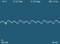
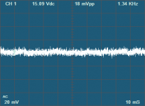
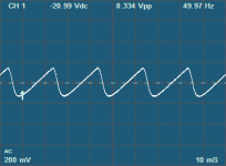
In attach you can see the positive rail and negative rail, in input and in output to the stabilizers.
I see that on the output of the stabilizer there is a nois of 18mV? Is this ok? Because in the datasheet I read that the nois should be 90uV.
Attachments

Nothing... that is not the problem...
I fixed some ground solder and now I'm again at the start point. +/-15V seems good and I can hear the hum in the output.
In attach you can see the positive rail and negative rail, in input and in output to the stabilizers.
I see that on the output of the stabilizer there is a nois of 18mV? Is this ok? Because in the datasheet I read that the nois should be 90uV.
Finally I solved the issue. I added 2 100nF ceramic capacitor between output and ground pin of both lm7815/7915 and the hum disappears.
So it seems that they are very important and cannot be replaced by 10uF elettrolitic.
alex, great piece of work here.
From Post #60, it doesn't appear that you've progressed the control/display side of things very much more for what is publicly available, as far as I can tell. Anything in the pipeline?
Your comment in Post #60 that "I have been thinking and prototyping but have not settled on a better solution", makes me think that maybe the aphorism attributed to Einstein/Sessions is appropriate:
Use the hardware to define the footprint and the form factor follows suit. It seems like you've opted for generic, readily available hardware - so, all that should be required is a BoM check for anything that's become obsolete and update if required.
The IR sensor can be hooked up via cabling so, that could be addressed by its own little window in a case's front panel or at one corner of the display with a bit of extra room to fit. Aesthetics could be managed by a section of tinted perspex to hide any unsightly aspects.
The only add-on that I can suggest, is you might want to add a pot to permit easy display brightness adjustment (if it's not already in the works).
Simple enough?
Next question, where and when can I get me some?
From Post #60, it doesn't appear that you've progressed the control/display side of things very much more for what is publicly available, as far as I can tell. Anything in the pipeline?
Your comment in Post #60 that "I have been thinking and prototyping but have not settled on a better solution", makes me think that maybe the aphorism attributed to Einstein/Sessions is appropriate:
As far as form factor goes, what I'm seeing in the proptotypes could be made to work. My suggestion is just go with it.... everything should be as simple as it can be but not simpler ...
Use the hardware to define the footprint and the form factor follows suit. It seems like you've opted for generic, readily available hardware - so, all that should be required is a BoM check for anything that's become obsolete and update if required.
The IR sensor can be hooked up via cabling so, that could be addressed by its own little window in a case's front panel or at one corner of the display with a bit of extra room to fit. Aesthetics could be managed by a section of tinted perspex to hide any unsightly aspects.
The only add-on that I can suggest, is you might want to add a pot to permit easy display brightness adjustment (if it's not already in the works).
Simple enough?
Next question, where and when can I get me some?
The prototype totally works. Using it in my own build is a no-brainer, and in fact I am working on a couple of boxes that will use it. It is making the prototype into a reasonable product that would fit in a number of use cases without re-programming that I have been struggling with.
As a way to move forward, I can offer assembled, programmed, tested boards pre-configured for a specific use case, say, MUSES (or other pre-selected) volume control, Apple remote, no display. Perhaps it would give me a better idea of what features are really needed, and what should be put of hold for now.
What do you say?
I ordered a Muses board an hour or so ago. I'd be happy for that order to be held back until you get the proto-boards sorted. Then pay the difference, in order to keep things tidy, together and the costs down.
This would give me motivation to get a balanced pre-amp built..
Regarding use case re-programming, you could apply the golden-arches/Maccas approach of offering a limited menu and catch the majority. Most people will make their own personal compromise and pick a burger that they'll eat (personally, I go bespoke but then never say never - there are times when desperation kicks in or there's no other choice).
Apple does something similar. Their closed ecosystem can be annoying but at least they minimise customer complaint over X not working with Y. Their kit generally interfaces well because they get the benefit of limiting choice by design.
Thank you for ordering! Give me a day to check what I can include with it as a controller.
As for a limited menu idea - thank you. I will think about a practical way to make it work.
As for a limited menu idea - thank you. I will think about a practical way to make it work.
Here is a one minute video showing the MUSES board and the controller in action.
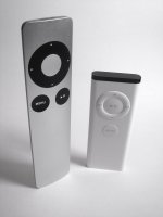
The display is a 4-digit alphanumeric LED display from Spark X, based on the HT16K33 controller. The volume level is displayed in percent, 0 to 100. The remote is an old (white) Apple remote; the newer aluminium one also works. Pairing and unpairing of the remote is supported.
The display is a 4-digit alphanumeric LED display from Spark X, based on the HT16K33 controller. The volume level is displayed in percent, 0 to 100. The remote is an old (white) Apple remote; the newer aluminium one also works. Pairing and unpairing of the remote is supported.
Attachments
Last edited:
Blue display in keeping with First Watt / Pass Labs - I like it.
Does the job. Looks and sounds good to me.
Does the job. Looks and sounds good to me.
As a follow on, any idea of the product longevity of the SPX-16426?
There's a comment on the linked page Qwiic Alphanumeric Display, Blue, SPX-16426 reads:
Even so, it looks like a good option. Sparkfun's documentation helps those slow on the uptake like me.
EDIT: Based on what I'm seeing here, my guess is that this piece of kit will hang around for a while.
There's a comment on the linked page Qwiic Alphanumeric Display, Blue, SPX-16426 reads:
Obsolescence is a moving target but is Sparkfun just trying to coax uptake or are they signalling something else? The listing at Mouser 474-SPX-16426 is telling me it's a new product, so hopefully that means it has a while to go before it gets the axe. Probably just mixed messages.We do not plan to regularly produce SparkX products so get them while they’re hot!
Even so, it looks like a good option. Sparkfun's documentation helps those slow on the uptake like me.
EDIT: Based on what I'm seeing here, my guess is that this piece of kit will hang around for a while.
Last edited:
Mouser in the US has only one in stock. Although the hardware design files are available from SparkFun, and the board can easily be replicated, the specific LED display they used is nowhere to be found. I guess I will need to switch to a display with longer term availability. Shouldn’t be too difficult.
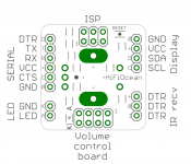
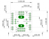
The controller board is 1.1x1.1in and carries six 0.1in pitch headers:
All connectors except LED carry power, so any one of them can be used to power the board, and the remaining ones - to provide power to other devices. Normally, the power is provided by the volume controller board, which carries a 5-volt regulator. In turn, the controller provides power to the IR receiver and display. Other arrangements may be possible. The controller board needs between 2.7 to 5.5 volts. The display from SparkX works with both 3.3 and 5 volts.
The attached pictures show the size of the board and connector placement.
- Eight pin in two rows for the volume control board
- Four pin for the display
- Three pin to connect an IR receiver for remote control
- Two pin for an LED (not used by the current firmware)
- Six pin, single row for a serial port
- Six pin, double row In-System-Programming (ISP) port
All connectors except LED carry power, so any one of them can be used to power the board, and the remaining ones - to provide power to other devices. Normally, the power is provided by the volume controller board, which carries a 5-volt regulator. In turn, the controller provides power to the IR receiver and display. Other arrangements may be possible. The controller board needs between 2.7 to 5.5 volts. The display from SparkX works with both 3.3 and 5 volts.
The attached pictures show the size of the board and connector placement.
Attachments
LDO Substitute
Recently ordered the PGA2310-board as it was exactly what I was looking for!
However, looking at the BOM at Mouser it seems the negative voltage regulator NJM7915FA has fallen out of grace and is no longer available to purchase.
As my electronics engineering skills are highly limited I humbly ask for advice. I think I've found a substitute in LM2990T-15/NOPB or perhaps the MC7915ACTG. Slightly lower current but hopefully not an issue. Typical schematic in datasheet deviated a little bit in capacitor values though so I though I'd better ask.
- Home
- Source & Line
- Analog Line Level
- Balanced Volume Controller / Line Stage