Hello all!
Since I've been shunned to far away lands without my usual gear I've been fooling around with some transistor-based circuits in an effort to learn and hopefully make something cool sounding.
After building some fuzzfaces and rangemasters I started 'hacking' together a schematic for a positive-ground germanium preamp. When I say 'hack', i really mean it. But, to my surprise, the dang thing works and already sounds pretty good, considering.
My current issues and questions are these:
1) The variable resistor between the two gain stages works just fine up until about 95% of maximum volume and then just squelches out until there's no volume. I tried different pot values (1k to 500k) and increasing voltage from 9v to 12v - no change.
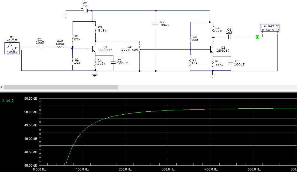
2) The frequency chart below says that this circuit is inherently dropping off pretty quickly under 200hz or so - how can I lower this? I want 80hz. (Note, I am using 2N527 transistors).
3) Since this is a total hack job, what could I do to improve it? I'm getting some good, colorful gain out of it at this point, but what are some options to try out and what have i done here that might be redundant or counter-productive?
Thanks and hope everyone's been doing great
Since I've been shunned to far away lands without my usual gear I've been fooling around with some transistor-based circuits in an effort to learn and hopefully make something cool sounding.
After building some fuzzfaces and rangemasters I started 'hacking' together a schematic for a positive-ground germanium preamp. When I say 'hack', i really mean it. But, to my surprise, the dang thing works and already sounds pretty good, considering.
My current issues and questions are these:
1) The variable resistor between the two gain stages works just fine up until about 95% of maximum volume and then just squelches out until there's no volume. I tried different pot values (1k to 500k) and increasing voltage from 9v to 12v - no change.
2) The frequency chart below says that this circuit is inherently dropping off pretty quickly under 200hz or so - how can I lower this? I want 80hz. (Note, I am using 2N527 transistors).
3) Since this is a total hack job, what could I do to improve it? I'm getting some good, colorful gain out of it at this point, but what are some options to try out and what have i done here that might be redundant or counter-productive?
Thanks and hope everyone's been doing great
Thanks, Radtech!!! That fixed the issue with the pot going out!
Funny thing is then the opposite was true - when i got down to about 5% volume it cut out entirely, but it looks like a small resistor in series with the ground lug fixed that.
Any suggestions for bringing the low-frequency down a bit?
Funny thing is then the opposite was true - when i got down to about 5% volume it cut out entirely, but it looks like a small resistor in series with the ground lug fixed that.
Any suggestions for bringing the low-frequency down a bit?
i would isolate the pot from dc current flow through it:
with a cap before and after the pot........;
bass......try to sim it without the 100uF electro`s (C2,C5).......
I see 2dB drop at 65Hz - provided this is a guitar stompbox there is no need to extend to a lower corner frequency. Not really
http://www.diyaudio.com/forums/analog-line-level/
Analog Line Level
Preamplifiers , Passive Pre-amps, Crossovers, etc.
Analog Line Level
Preamplifiers , Passive Pre-amps, Crossovers, etc.
Unfortunately, I have yet to find a germanium spice model that is actually any where close to being correct. Notice in your sim the 635mV b-e junction voltage, should be 400mV at most, 350mV typical, for germanium. Your operating points are probably no where near what the sim shows, which are not quite right any way. This is a math and measure design situation where spice just doesn't get it (near) correct.
Attached is the only model that is any where close that I found here on the forum so credit goes to that member.
Attached is the only model that is any where close that I found here on the forum so credit goes to that member.
Attachments
Last edited:
@Old'n'Cranky: Thank you for finding the right spot for my post!
@mjf: Removed the 100uf caps from the sim; it appeared to only drop the gain. Going to try isolating the other side of the pot with a cap.
@voltwide: not just for guitar, in fact i'm trying to get the low-end happening so it can be used on kicks and bass guitar, too. going to add 48v phantom.
@jerluwoo: thanks for that. i don't know if i can load that into CircuitMaker yet. I know they don't have any AC128s (or my 2N527's) in their component list. Is there a better freebie sim i should be using?
You need a Ge model to set the DC bias points. Since you have the Ge part already working, and can observe DC voltages, there is less need to model the DC condition.
The _AC_ conditions will not be very different with hi-gain Ge or Si transistor. You CAN optimize clipping and frequency response with any modern jellybean.
Since SPICE capacitors cost ZERO, you can play with the bass response until happy. Replace one cap at a time with 100,000uFd. Does bass get better?
In this case-- not right away. The bass loss is mostly the emitter caps. Super-size one, the other is still bass-shy, and you might not notice the change of slope in the cut-band. (Especially with that puny 2.5dB scale range; look at least 20dB down.)
But wait! "Surely 100uFd is ample for 1K resistors!?" No, that's where gain picks-up. It drops-off when 100uFd equals 1/hIE or re of the transistor. At about 1mA, re is about 30 Ohms (Shockley's Law). 100uFd+30r is 55Hz. Two of those cascade is likely to be 70Hz, about like your graph.
I have real doubt you need ALL THAT gain. Even for guitar-mangle. I'd be thinking of small 50-200r resistors in series with Ce. Which also means Ce does not have to be so very big. Also raises input impedance from very-low to sorta-decent. But may mask the curvature of Ge.
Option #1- To add the model to circuitmaker rename the .txt extension to .lib and copy it to /circuitmaker/models/ directory. Open circuitmaker and click the "macros" button at the top and choose "Macro Utilities" from the dropdown list. A dialog box will appear that should have npn transistor already chosen. Choose "PNP Trans:B from the lower left box. Now click "model data" at the lower right and again another dialog box will appear. Click "open" at the lower left and navigate to where you copied the model to and open. The model will appear in the far left box. Highlight the model, fill in the description, package name, and pin numbers (none of which have any effect so they can just be whatever) and then choose add at the lower left and exit the dialog boxes and there you g ption #2- Place the generic NPNor PNP model on the work area. Double click it and choose edit. In the next dialog box you can manually edit the parameters to match those of your chosen model. Choose a name for your edited model and click ok. Done. The first option is actually easier if the model is compatible, which this model is.
ption #2- Place the generic NPNor PNP model on the work area. Double click it and choose edit. In the next dialog box you can manually edit the parameters to match those of your chosen model. Choose a name for your edited model and click ok. Done. The first option is actually easier if the model is compatible, which this model is.
Last edited:
@PRR: Thanks a lot for the education and suggestions. I tried increasing those emitter caps to 100,000uf - it didn't help with the bass response, but did act like a low pass filter on all the high frequencies.
@jerluwoo: thanks so much for explaining that. i tried the first solution but even after i entered in the various values it would not let me add it. I'll have to see about the 2nd method.
double drats!!
regarding the gain, i would like to use it for mics as well as DI. my understanding was that I need around 60db of gain to handle most any mic (including some ribbons).
my point with this is to have a 'mostly' clean preamp (with color) for mics and DI, with the ability to push it into Ge fuzziness. this is obviously for color and not a precision preamp.
thanks again for the input, everyone; this is my first foray into designing/building a solidstate pre.
...I tried increasing those emitter caps to 100,000uf - it didn't help with the bass response, but did act like a low pass filter on all the high frequencies. ...
You are doing something wrong.
It isn't clear if you found real 100,000uFd caps for your build, or just simulated it and got a graph.
As I implied, *both* stages have a 50Hz cut, so you need to up-cap *both* to really make a change. (And 1,000uFd will be plenty for a real build.)
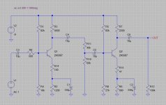
Anything more than a few hundred microfarads for the emitter bypass caps isn't going to make all that much of a difference. If you want to flatten the response you can add some degeneration. Make both caps something like 330uF, then add some non-bypassed resistance in the emitter circuits. This will bring down the overall gain, but flatten the frequency response.
Attachments
hey radtech - thank you so much for sim'ing that and for the information. above and beyond and super helpful.
i tried a few of the changes and didn't get the intended result - i'm going to rebuild the sim from scratch based on yours and see if i can match these results.
by the way, i think the battery should be reversed on your schemo (positive ground)?
thanks again and will post back soon.
i tried a few of the changes and didn't get the intended result - i'm going to rebuild the sim from scratch based on yours and see if i can match these results.
by the way, i think the battery should be reversed on your schemo (positive ground)?
thanks again and will post back soon.
The voltage source is correct, it is set for -9V, so the terminal marked "+" is actually negative. You could flip it over and set it to 9V if you want, I just prefer to keep all my voltage sources oriented in the same way with + up and - down.
I ran this simulation with the germanium transistor model that jerluwoo posted earlier in this thread and I found that the low frequency response was better but high frequency response wasn't very good. I put a low value capacitor across each of the degeneration resistors (R14 & R15) and was able to get it better, I don't recall what values I used, you can experiment with different ones, something like 0.001uF to 0.1uF.
Play around with it in the simulator to see how different values affect the response, then when you build it you'll still to tweak things a bit but you'll have a better understanding of what to try.
hey Radtech,
I went back to the sim and popped in the values you had, then played around a bit with some values.
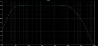
Putting those caps across R14 and 15 really did the trick on the top end. It's flat as a rail now past 20k, and only cuts about a half db by the time it reaches down to 50hz. I used 4.7nf caps. Changing R4 to 680r instead of 1.2k helped, as well.
Now to order some 330uf caps...Thank you so much!
It's showing around 60db of gain on the sim, which is a target range minimum for ribbon mics.
Question - how could I determine the input impedance?
I went back to the sim and popped in the values you had, then played around a bit with some values.
Putting those caps across R14 and 15 really did the trick on the top end. It's flat as a rail now past 20k, and only cuts about a half db by the time it reaches down to 50hz. I used 4.7nf caps. Changing R4 to 680r instead of 1.2k helped, as well.
Now to order some 330uf caps...Thank you so much!
It's showing around 60db of gain on the sim, which is a target range minimum for ribbon mics.
Question - how could I determine the input impedance?
I'm getting somewhere around 6K impedance, but I don't know exactly what circuit and transistors you are using in your simulation.
What are your requirements? What input signal level, impedance and gain are you looking for? This is a pretty basic circuit, I'm not sure how well it will ultimately perform.
What are your requirements? What input signal level, impedance and gain are you looking for? This is a pretty basic circuit, I'm not sure how well it will ultimately perform.
Thanks a lot for checking that for me.
I would hope to use it on a range of sources, but primarily microphones.
Out of my mics the AT3060 is probably the one with the highest impedance at 400ohms.
(Spec sheet is here: http://recordinghacks.com/pdf/audio-technica/at3060_english.pdf)
I understand you should have 3-4 times the mic impedance on your preamp.
When you say it may not perform well, in what way do you mean? Gain? Freq response? Clarity?
Thank you for your help!
- Status
- This old topic is closed. If you want to reopen this topic, contact a moderator using the "Report Post" button.
- Home
- Source & Line
- Analog Line Level
- Germanium Preamp Questions