Hello,
I'm attempting to lay down an input board accepting both balanced xlr inputs and unbalanced inputs from TS jacks. Obviously, it's inspired by Bruno Putzeys' suggestions, epecially in here.
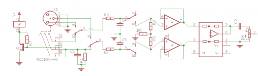
Combo jacks from Neutrik or amphenol are great for that but since the input section isn't exactly the same for xlr and ts (R1 is the culprit, see schematic), I need a way to switch in between the two inputs. An external switch would be possible of course but an automatic method would be best. So here is what I came up with:

If we concentrate on what's at the left of R3/R4, we've got the switched combo jack (could be a ncj9 btw). When an xlr is inserted, the switches are closed, the base of Q1 is taken to gnd (or near to, R1 being low in value), the relay is active and the xlr is the active input. When TS jack is inserted, the base of Q1 goes to v+, the relay is inactive and the xlr is taken out of the picture.
Did I miss anything obvious ? Or did I over-designed the thing ? I'd appreciate any suggestions or corrections on this. 🙂
I'm attempting to lay down an input board accepting both balanced xlr inputs and unbalanced inputs from TS jacks. Obviously, it's inspired by Bruno Putzeys' suggestions, epecially in here.
Combo jacks from Neutrik or amphenol are great for that but since the input section isn't exactly the same for xlr and ts (R1 is the culprit, see schematic), I need a way to switch in between the two inputs. An external switch would be possible of course but an automatic method would be best. So here is what I came up with:
If we concentrate on what's at the left of R3/R4, we've got the switched combo jack (could be a ncj9 btw). When an xlr is inserted, the switches are closed, the base of Q1 is taken to gnd (or near to, R1 being low in value), the relay is active and the xlr is the active input. When TS jack is inserted, the base of Q1 goes to v+, the relay is inactive and the xlr is taken out of the picture.
Did I miss anything obvious ? Or did I over-designed the thing ? I'd appreciate any suggestions or corrections on this. 🙂
Attachments
00940
I don't understand Your problem. If You use a plastic TRS (Stereo) female, You can use it for unbalanced connections if you insert a TS (mono) jack, since the sleeve and ring will be shorted and the sleeve will be also always isolated from chassis ground. On every gear I know TRS and XLRs are connecter in parallel. (Usually there are resistors in series on the TRS for Line level reducing for ex between MIC & Line on consoles). If you need to address the pin 1 problem just use metallic parts and wire pin 1 to chassis. Sorry I don't understand the R1 problem ? Combos are TRS and not TS. Just use the correct cable.
I don't understand Your problem. If You use a plastic TRS (Stereo) female, You can use it for unbalanced connections if you insert a TS (mono) jack, since the sleeve and ring will be shorted and the sleeve will be also always isolated from chassis ground. On every gear I know TRS and XLRs are connecter in parallel. (Usually there are resistors in series on the TRS for Line level reducing for ex between MIC & Line on consoles). If you need to address the pin 1 problem just use metallic parts and wire pin 1 to chassis. Sorry I don't understand the R1 problem ? Combos are TRS and not TS. Just use the correct cable.
The idea is to have an input section I can use both for balanced and unbalanced sources. It's easy to convert an rca cable into a rca to TS with a pair of simple adapters. Combo don't come with TS indeed, otherwise I'd use that, but a TRS can serve as a TS.
The problem with R1 is that I can't simply // the trs and the xlr sections of the combo jack otherwise the cold pin of the xlr will be grounded.
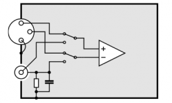
In other words, I just want to do this (it comes from p5 of the pdf linked to in post 1), but with an automatic switch and using a single connector to save space:

It's for domestic hifi btw, not PA use. So I'll have a mix of earthed and non-earthed sources.
The problem with R1 is that I can't simply // the trs and the xlr sections of the combo jack otherwise the cold pin of the xlr will be grounded.
In other words, I just want to do this (it comes from p5 of the pdf linked to in post 1), but with an automatic switch and using a single connector to save space:
It's for domestic hifi btw, not PA use. So I'll have a mix of earthed and non-earthed sources.
Attachments
You have (unknown amount of) DC on your 1/4" sleeve. Not sure this will always be benign.
What is your apparent problem? You want *less* gain for 1/4" than for XLR? In studio we just use a wide-range GAIN knob (your R2+R5, do not know what R8 does). But studio is prone to more range of levels than hi-fi, so you seem to resist that path.
What is your apparent problem? You want *less* gain for 1/4" than for XLR? In studio we just use a wide-range GAIN knob (your R2+R5, do not know what R8 does). But studio is prone to more range of levels than hi-fi, so you seem to resist that path.
I'm awfully bad at explaining this thing...
No, it's not a mater of gain, it's a matter of inserting a ground loop breaker (R1 in // with C1) in between the rca return and chassis when using an unbalanced source. Quoting Putzeys (from the paper linked in post 1): "the only reason why one should consider including an RC combination is to keep the signal within the common mode range of the input circuit (remember that the source may be floating) and to keep RFI that’s been picked up by the RCA cable out of the box." R1 is quite low in value, about 100, which is why I can't connect it to pin3 of the xlr.
Yes there is a tiny bit of DC on the sleeve but it's not that bad really. The relay is a sensitive signal one so it doesn't need a lot of current. About 17ma for a 9V one. So little base current is needed. In turn that means we can make R7 quite big, 33k is no problem with a bc807.
When nothing (or a xlr) is inserted, the sleeve is in contact with a voltage divider made of 33k and 100r. Assuming a supply of 9V, that's 31mV. When a jack is inserted, it breaks the voltage divider. The switch is linked to 9v, the sleeve to chassis through a 100r resistor. There is no more DC on the sleeve at that point.
R2-5-8 are simply the input bias DC resistors for the following inamp, they are not for gain. That three resistors network is used in THAT appnotes and by Putzeys among others (values for R2-R5 are 470k, 1meg for R8).
Edit: there is a mistake in the first schematic... r7 should return to the supply, not to the relay negative terminal...
Edit2: since I cannot edit the first post, here it is
Attachments

Last edited:
Will You be using 100 m of cable at home ?? Platin or Gold cables and Milliondollar Amplifiers with 0.00000000000000001 % distortion or exotic Valve equipment and speakers... Don't overcomplicate things. .. I believe inserting jacks and connectors with DC will produce audible thumps. You want to isolate, but then there is a transistor with collector connected to Ground a relay etc on the line...Just use a mic cables (3 wire) and not RCA cables (2 wire) to convert RCA to XLR or TRS. Ground the cold wire on the RCA side. I do DJ events and I use long cables up do 200m to drive speakers in the garden and at a venue I have a cable with a star distribution arrangement with 6 boxes with XLRs and over 150m cable and all works fine. I have seen some adapters with some sort of switch when You plug a XLR in, isolated from the main 123 pins. Perhaps You can use this switch to drive a relay. Or a microswitch correctly positioned...
Last edited:
Agree: don't overcomplicate.
I have hardly ever used that form of "ground breaker" in decades of home and professional audio.
A differential input normally takes an unbalanced input no problem.
This can be done even when there is common-mode voltage. I had a stage and a control booth that were 3V apart in power ground. Differential input upstairs took signals from the stage cleanly. If you really have >10V common mode difference in small audio, I'd call that a Power Problem. And I am not sure your R-C network would help? Ah, I see what he is saying. Then you can put the R-C in XLR pin 1 also.
Ok let's try this:
Get a laptop PC with a 3 prong grounded PSU.
Connect it to a grounded harness and to an amplified speaker or Amp /mixing desk with a 3.5 jack to RCA or XLR a few meters away.
You will hear the HD spinning and Your mouse moving even with the PC volume turned down...
Now insert this Bruno "ground breaker" and it won't solve Your problem. I've tried !!
What will solve the problem is connecting the laptop or speaker to an ungrounded harness. Try it !!
On my DJ laptops I use a lamp desk switch on the PSU input cable to cut the ground.
Last edited:
MAAC0: I simply use a stereo DI in the situation you describe. Alternatively, a usb dac with isolated USB lines.
Anyway, this scheme is supposed to be used with floating class II devices (non-earthed; pretty much your laptop once earth-lifted, not before) mixed with more than one class I devices (earthed). This kind of ground loop breakers can help if you have a more complex chain with small circulating currents, not in nightmare situations with one very bad source as you describe.
Btw, I do not own very fancy equipment. But I do use mostly headphones which are sensitive enough to pick the slightest residual noise.
I dropped the idea anyway, I'm drawing a more simple input selector.
Last edited:
- Status
- Not open for further replies.
- Home
- Source & Line
- Analog Line Level
- Controlling a relay with a combo jack (xlr-ts input)