I decided to start a separate thread to understand more about the buffer design by Dennis Feucht.
In the article he mentions some techniques to improve noise and DC offset from the buffer.
There is a unique issue with BF862 when I try to follow offset voltage optimization. In the given example Dennis describes how to identify the zero- drift Vgs for Jfets from ID-Vgs plots. Unfortunately BF862 does not provide one such plot with different temp. Estimation by adding 0.7to 0.8V to pinch off voltage(Vp) is also tough because Vp is -0.8V for BF862.
So my first question, how can I estimate zero-drift point for BF862?
In second part of his article he describes how to reduce thermal noise. In general setting bias point for maximum power dissipation at quiescent point in both Jfets reduces thermal noise.
So my operating points are
quiescent ouput voltage VL= 1.2V (to my amp)
Input impedence of Amp RL= 50Kohm
So my second question
I am unsure what is I0= ? . Is it the current through both jfets decided by RSl=RSu=Rz?
If so I want to set the quiescent point at 6mA. My batch of BF862 are having a Idss=12.5 to13.5. I was told before to set the ID in saturation region to avoid issues with supply voltage ripple. But most resources does not recommend doing that. This link is about biasing source follower configuration,pls look at Page 7 in attached document.
http://www.colorado.edu/physics/phys3330/phys3330_fa11/pdfdocs/AN102FETbiasing.pdf
Awaiting expert opinions.
Attachments
Last edited:
I think the 0.7V to 0.8V for zero tempco comes from Borbely, or from similar thinking to Borbely.
I think Borbely was not correct in suggesting that fixed value of 0.63V above Vp.
I found in what little testing I did with lsk170 that near zero tempco varied with Idss of the device and could be lower than 0.5V and higher than 0.8V
I0 is the bias current (standing current) you choose to set.
I think Borbely was not correct in suggesting that fixed value of 0.63V above Vp.
I found in what little testing I did with lsk170 that near zero tempco varied with Idss of the device and could be lower than 0.5V and higher than 0.8V
I0 is the bias current (standing current) you choose to set.
Last edited:
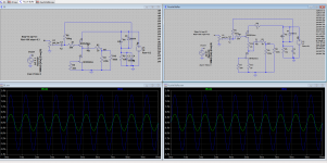
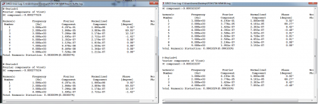
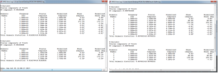
I went ahead and did a simulation with Classic B1 and and modified by Feucht's recommendations.
B1 shows more THD in simulation than Feucht's design of B1. More notable in higher V input at 1.4V.
B1 shows more THD in simulation than Feucht's design of B1.
More notable in higher V input at 1.4V.Attachments
- Status
- This old topic is closed. If you want to reopen this topic, contact a moderator using the "Report Post" button.