A while back I got some help on here with an active Baxandall linestage: http://www.diyaudio.com/forums/tubes-valves/301063-active-bax-preamp-review-request.html
I had some PCBs made and I'm happy to say it works very well as far as my ears can tell. Even the measured frequency response is very close to SPICE models. It is installed in my preamp along with Merlin's phono stage - all feeding in to a DCPP. I'll post details at some point in the future once I've ironed out a few niggles...
However, my sources don't drive the DCPP to anywhere near full output. I'm at 50/64 on the volume control watching TV at normal level, e.g. So I'd like a version of my preamp design with ~6dB gain.
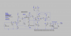
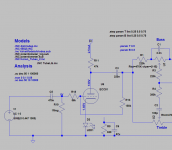
Attached is what I've come up with.
1st stage is ECC81 gain stage with red LED biasing and local NFB to reduce the gain.
2nd & 3rd stages are the active Baxandall stack using another ECC81. The feedback & output taken from the 3rd stage cathode.
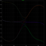
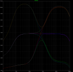
Using lots of NFB, I assume, means distortion will be reduced. Simming this gives ~6dB gain and shows fairly flat at central settings, also attached.
Does anyone see any problems / improvements with this scheme? Would there be a better way to achieve what I want?
Thanks!
I had some PCBs made and I'm happy to say it works very well as far as my ears can tell. Even the measured frequency response is very close to SPICE models. It is installed in my preamp along with Merlin's phono stage - all feeding in to a DCPP. I'll post details at some point in the future once I've ironed out a few niggles...
However, my sources don't drive the DCPP to anywhere near full output. I'm at 50/64 on the volume control watching TV at normal level, e.g. So I'd like a version of my preamp design with ~6dB gain.
Attached is what I've come up with.
1st stage is ECC81 gain stage with red LED biasing and local NFB to reduce the gain.
2nd & 3rd stages are the active Baxandall stack using another ECC81. The feedback & output taken from the 3rd stage cathode.
Using lots of NFB, I assume, means distortion will be reduced. Simming this gives ~6dB gain and shows fairly flat at central settings, also attached.
Does anyone see any problems / improvements with this scheme? Would there be a better way to achieve what I want?
Thanks!
Attachments
For a start I would use a 1k2 with a decoupling capacitor in the cathodes not non linear diodes. Remove the feedback on the first stage as 220n and about 1Meg will possibly oscillate.
Use an ECC83 not 81 and why use a cathode follower in the last stage, it just makes things more complex for no reason.
Use an ECC83 not 81 and why use a cathode follower in the last stage, it just makes things more complex for no reason.
Decrease R18 from 470k to 220k. This should increase the overall gain by about 6dB more.
Thanks - yes I had done some tinkering with both R18 & R13 to get flat response and the gain needed. 220k & 560k gives me just over 6dB.
Would 12dB not be way too much? Maybe it's a trial and error situation - would be nice to have a bit more travel on the volume knob!
Would 12dB not be way too much? Maybe it's a trial and error situation -
would be nice to have a bit more travel on the volume knob!
If you normally use a phono stage, usually the line amp should have some gain,
somewhere from 6-14dB. If only CD is used, then 0dB should be ok for the line stage.
Few power amps need more than the 2Vrms from a CD player to reach their full output.
Last edited:
For a start I would use a 1k2 with a decoupling capacitor in the cathodes not non linear diodes. Remove the feedback on the first stage as 220n and about 1Meg will possibly oscillate.
Use an ECC83 not 81 and why use a cathode follower in the last stage, it just makes things more complex for no reason.
Interesting suggestions. It's this sort of input I appreciate - that a 220n and the feedback resistor could cause an oscillation. I didn't have much luck with local NFB in a guitar amp...
I've had a good experience with LEDs thus far and like the smaller footprint. I see there's a lot of debate on one versus the other. And there's the part about valves ageing. I'll see if I can fit the extra components on the PCB.
Would the ECC83 not give way too much gain?
The CF on the last stage was a bit gratuitous. I can't remember the reasoning but I think something to do with impedance...
If you normally use a phono stage, usually the line amp should have some gain, somewhere from 6-14dB. If only CD is used, then 0dB should be ok for the line stage. Few power amps need more than the 2Vrms from a CD player to reach their full output.
Yes, I had assumed my sources (other than phono) were line level... Silly mistake. The phono stage works really well in conjunction with the linestage, but I'm OK having to adjust the volume when I'm playing a record.
I mostly use the output from my TV (via an optical to RCA convertor box). And then I use a sound card + RaspberryPi for music. So atypical, and seemingly nowhere near 2Vrms...
Why is response rising below 30Hz? (I think I see why, but it is your project.)
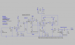
Thanks - yes, I can flatten that by decreasing C3 to 100n. I had kept it at 220n to match C10, the feedback capacitor for the tone stack. Latest schematic and plots attached.
Have you considered thermal noise in R18 and the tone control network? May be OK for line level, but you should do the sums just to check.
This is a worry. My currrent build is very quiet (well, there is no perceptible hiss when in use) so it would really be the addition of R18 in the signal path. I'll likely get some expensive Vishay/Dale low noise ones to go there...
The interaction of R18, R13, C3 & C5 is very interesting. If I halve R18 & R13 I need to double C3 and increase C5 to get a similar response as attached. I guess this is the changing impedance at work?
If anyone can suggest a simpler way to get 6-12dB gain please do let me know!
Attachments
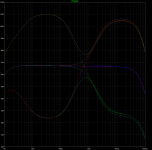
By way of example, here is the sweep when R18 and R1 are 56k and 150k. So lower R18 = lower noise. But this alters the impedance to the previous / next stage. The modelling may not give the whole story?
e.g.: to get a flatter response C5 needs to be increased. Going up to 680n gives practically flat. 470n seems OK.
e.g.: to get a flatter response C5 needs to be increased. Going up to 680n gives practically flat. 470n seems OK.
Attachments
C3 and C10 do not need to match, as they are inside different feedback loops so are not directly comparable. There may be some advantage in ensuring that the Baxandall network is symmetric, by adding another capacitor after C3 but outside the first stage feedback loop.
R18 thermal noise cannot be eliminated by choosing any particular resistor type. However, reducing its value as you have now done will reduce thermal noise. It will increase the load on the source, but this should not matter.
R18 thermal noise cannot be eliminated by choosing any particular resistor type. However, reducing its value as you have now done will reduce thermal noise. It will increase the load on the source, but this should not matter.
- Status
- This old topic is closed. If you want to reopen this topic, contact a moderator using the "Report Post" button.
- Home
- Source & Line
- Analog Line Level
- Active Bax Preamp with 6dB gain - design critique