In this preamp -
http://chemelec.com/Projects/Preamp-1/Preamp-1.png
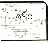
The gain is set by R1/R2. When I use the default values R1 = 680k and R2= 470ohm. The gain appears to be very low.
What values of R1 and R2 should I use to get a gain of at least 8-10 db. Possibly enough to drive a power amp.
http://chemelec.com/Projects/Preamp-1/Preamp-1.png
The gain is set by R1/R2. When I use the default values R1 = 680k and R2= 470ohm. The gain appears to be very low.
What values of R1 and R2 should I use to get a gain of at least 8-10 db. Possibly enough to drive a power amp.
Hey that looks EXACTLY like James Bongiorno's "Build a Distortionless Preamplifier" project from the June 1972 issue of Popular Electronics, except turned upside down! You've even got the (stupid IMHO) two-diode bias trick.
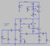
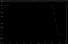
If you get rid of the diodes and install a proper ladder bias network as shown in Figure 2 below, you can get large signal swings and pretty decent bandwidth out of the thing: Figure 3.
The gain of the Figure 2 circuit is (R7+R5)/R5 . As shown here, gain = 2.0 which is +6dB.
If you get rid of the diodes and install a proper ladder bias network as shown in Figure 2 below, you can get large signal swings and pretty decent bandwidth out of the thing: Figure 3.
The gain of the Figure 2 circuit is (R7+R5)/R5 . As shown here, gain = 2.0 which is +6dB.
Attachments
In this preamp -
http://chemelec.com/Projects/Preamp-1/Preamp-1.png
The gain is set by R1/R2. When I use the default values R1 = 680k and R2= 470ohm. The gain appears to be very low.
What values of R1 and R2 should I use to get a gain of at least 8-10 db. Possibly enough to drive a power amp.
Do you have 1/2 of supply voltage minus 0.6V at "TP"?
This is the key thing to begin with.
@vazaichenko
Nope i get roughly .2 volts at TP. Actually i replaced the 680K resistor with a 2k resistor to limit the gain. Also replaced the 2n5088 with BC 549C and 2n5087 with BC 560.
I have also replaced the bias resistor 3k9 with 47k since i am using a 34 volt supply. The voltage at the end of the 47k resistor is roughly 1.5 volts
Could the resistor replacement be the cause of the problem?
Last edited:
Do you realise that the design is for a phono preamp and not a line stage ? It can all be altered to do what you want but just changing resistors is going to upset the DC operating point.
Also... why is the midpoint adjust preset in the original circuit (link in post #1) configured to alter the gain as well as the DC operating point ?
Also... why is the midpoint adjust preset in the original circuit (link in post #1) configured to alter the gain as well as the DC operating point ?
Do you realise that the design is for a phono preamp and not a line stage ? It can all be altered to do what you want but just changing resistors is going to upset the DC operating point.
Also... why is the midpoint adjust preset in the original circuit (link in post #1) configured to alter the gain as well as the DC operating point ?
Good question but I really don't know why. What I believe is the the gain is set by r1 and r2. The 20 k is used to set the midpoint. I don't think you can actually set gain via the 20k pot.
You´ve just thrown DC working points through the window.Actually i replaced the 680K resistor with a 2k resistor
The gain adjustment method is shown, it even has 2 examples (Mic-ceramic/Phono) , both do NOT mess with DC setup because they are connected to the rest of the circuit through DC blocking caps.
Not really, for AC you have a resistance variable between 15 and 40k in parallel with 470 ohms, so no practical effect.Also... why is the midpoint adjust preset in the original circuit (link in post #1) configured to alter the gain as well as the DC operating point ?
Note: you were suggested a working preamp circuit, doing exactly what you asked for, in another thread.
Not sure why you prefer wild designs, unsuitable for what you claim to need, and then botch them.
Last edited:
You´ve just thrown DC working points through the window.
The gain adjustment method is shown, it even has 2 examples (Mic-ceramic/Phono) , both do NOT mess with DC setup because they are connected to the rest of the circuit through DC blocking caps.
Not really, for AC you have a resistance variable between 15 and 40k in parallel with 470 ohms, so no practical effect.
Note: you were suggested a working preamp circuit, doing exactly what you asked for, in another thread.
Not sure why you prefer wild designs, unsuitable for what you claim to need, and then botch them.
I just tried to limit the Gain to 6 db rather than 60db as provided by this circuit. I was just experimenting.
Maybe i will botch a 100 more before i start learning
")
In order to learn from "botching" you first have to do some learning. Get a circuit which works (i.e. build it exactly as given) then fiddle with it and see what changes. You can't learn much from building a circuit which doesn't work either because it is a bad circuit or because you made changes you don't understand.
This circuit is not intended or designed to go as low as 6dB gain. It is a high gain preamp for very small signals, and somewhat idiosyncratic at that.
This circuit is not intended or designed to go as low as 6dB gain. It is a high gain preamp for very small signals, and somewhat idiosyncratic at that.
In order to learn from "botching" you first have to do some learning. Get a circuit which works (i.e. build it exactly as given) then fiddle with it and see what changes. You can't learn much from building a circuit which doesn't work either because it is a bad circuit or because you made changes you don't understand.
This circuit is not intended or designed to go as low as 6dB gain. It is a high gain preamp for very small signals, and somewhat idiosyncratic at that.
Point taken. i did actually build this circuit right. This attempt was just to make my own mods and see if that works. Which it didn't !
A tip: when modding a circuit make a small change not a big one. You might then have seen that the resistor change ruined the DC bias and stopped the circuit from working.
Another tip: always check DC conditions. If the designer says 'point X must be Y volts' then he may be right.
Another tip: always check DC conditions. If the designer says 'point X must be Y volts' then he may be right.
Good question but I really don't know why. What I believe is the the gain is set by r1 and r2. The 20 k is used to set the midpoint. I don't think you can actually set gain via the 20k pot.
The preset and its series resistor is effectively across R2 as far as gain calculations go. So it adds a variable that will cause the gain to be different for each example built.
If you write your own basic specification down first such as:
1/ Supply voltage.
2/ Gain required.
3/ Minimum acceptable input impedance.
4/ Impedance of the load it has to drive.
Then you stand a much better chance of designing something that is ideally suited to what you want.
This circuit is not intended or designed to go as low as 6dB gain.
The variant in post #3 has +6dB gain, 16 MHz bandwidth, and 57 degrees of phase margin. Changing C3 from 15pF to 33pF gets you +6dB gain, 9MHz bandwidth, and 71 degrees of phase margin. In my opinion it works fine at +6dB of gain.
The key word is "variant" i.e. slightly different circuit, not just change a few component values. Your variant has much higher quiescent currents, a stabilised supply rail and a simpler bias method. As DC and AC feedback are mixed together, I assume that it was designed for low gain while the OP's original circuit was designed for high gain.
The preset and its series resistor is effectively across R2 as far as gain calculations go. So it adds a variable that will cause the gain to be different for each example built.
If you write your own basic specification down first such as:
1/ Supply voltage.
2/ Gain required.
3/ Minimum acceptable input impedance.
4/ Impedance of the load it has to drive.
Then you stand a much better chance of designing something that is ideally suited to what you want.
Yes. That makes sense.
The key word is "variant" i.e. slightly different circuit, not just change a few component values. Your variant has much higher quiescent currents, a stabilised supply rail and a simpler bias method. As DC and AC feedback are mixed together, I assume that it was designed for low gain while the OP's original circuit was designed for high gain.
How about i leave the resistors as they are and increase the capacitor values especially the coupling capacitor (2.2uf ) to something of a higher value say 47uf and increase all others to get a good low frequency response.
Would that work ?
Would that work ?
Not really.
What are you trying to achieve ? You mentioned wanting it to drive a power amp so that sort of puts the output voltage around say 2v volt rms as a maximum.
So what are you feeding the preamp from ? A record deck or a line level source such as a CD player ?
- Status
- This old topic is closed. If you want to reopen this topic, contact a moderator using the "Report Post" button.
- Home
- Source & Line
- Analog Line Level
- Preamp Gain