Full disclosure: I'm an applications engineer for Texas Instruments Precision Analog
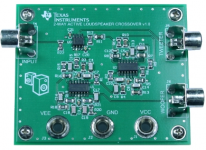
I've recently published a reference design for an active crossover for two-way loudspeakers. The design incorporates 4th-order Linkwitz-Riley filters, a 3rd order allpass section for tweeter time alignment, and a shelving circuit for baffle step compensation. It can be a very versatile PCB for active crossovers.
The PCB gerbers are available in the design file and can be submitted to the manufacturer of your choice. The design file also includes schematics, simulation files, and a software install file. The op amps I used for the design (OPA1602 and OPA1604) can be sampled for free as well.
The page for the design is here: Analog, Active Crossover Circuit for Two-Way Loudspeakers - TIPD134 - TI Tool Folder
The design document can be downloaded here: http://www.ti.com/lit/pdf/tidu035
PCB Gerbers and other files: http://www.ti.com/lit/zip/tidc033
I apologize in advance if this violates the forum policies, because the document and PCB files may be useful to hobbyists I was hoping this post wouldn't be viewed as overtly commercial.
This is a nice design. Unfortunately, it is more or less limited to those drivers it was designed for or very similar driver. Other drivers might have sufficiently different response and z-offset that the crossover might not work very well. Because the implementation of the circuit uses SMD devices, the DIYer would not easily be able to modify all of the components to change crossover corner frequencies and delay. Otherwise, I like it.
Thanks for your comment. You're correct that the passive component values are calculated for those specific drivers. However, the PCB itself implements a fairly universal circuit topology. The gerber files are available for anyone to submit to a PCB manufacturer and then install whatever passive components or op amps that they chose. The 1206 footprints used for the passive components shouldn't be difficult for even the soldering novice.
I really like the design! Have you considered integrating it onto a PCB with a 2-channel amplifier, and maybe add provisions for notch filters?
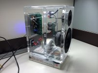
Thanks! I have integrated this design onto a PCB with 2 LM3886s and a volume control circuit in order to build some powered studio monitors (unfortunately no notch filters at the moment). In the future I'll be writing up a document on this design as well and hosting the gerber files in a similar manner.
Here is a picture of the powered studio monitor with an acrylic enclosure:
Attachments
Thanks! I have integrated this design onto a PCB with 2 LM3886s and a volume control circuit in order to build some powered studio monitors (unfortunately no notch filters at the moment). In the future I'll be writing up a document on this design as well and hosting the gerber files in a similar manner.
Here is a picture of the powered studio monitor with an acrylic enclosure:
I would very much appreciate these.
For the not-very-good-at-PCB-design, could you explain briefly your thoughts on grounding, power, and avoiding weird op-amp issues?
I stumbled onto the TI pages while researching line level BSC solutions. Since I'm using this with a full range driver, I'm going to prototype with an OPA1602 on breadboard. My signal chain: Raspberry Pi --> HRT Microstreamer --> (OPA1602 BSC circuit) --> TPA3122 amp --> Peerless TC9FD desktop speakers.
Engineering an OPA1602-based BSC circuit should be simpler than figuring out how enable a graphic equalizer solution in my Raspberry Pi.
Engineering an OPA1602-based BSC circuit should be simpler than figuring out how enable a graphic equalizer solution in my Raspberry Pi.
Linkwitz-Riley of crossover
This is a great project. There are many considerations made by John. Thanks a lot.
Nevertheless I stumbled about the dimenson of the LP and HP.
In contrast to Linkwitz-Riley topologie the value of the resitors are quite different than I expected.
In regard to linkwitz-riley dimension it should be R(R1=R2=R18=R19=R20=R21) and R3=R4 =R/2. In this case the phase difference amounts to 360°, i.e. the two drives appear in phase, albeit with a full period time delay (360°) for the low-pass section.
So could you give a hint for this dimension?
Exciting thread, toward a possible workhorse
John Caldwell did a very good design,
with exactly what functions are really needed to accommodate speakers for high end monitors: LP4, HP4, Baffle Step, and Tweeter delay.
Now, to generalize the possibility of what is provided, evolutions of Cut-Off frequencies and other parameters could be achieved by tuning a few resistors (keeping the original capacitors) as 1% resistors are easier to find (with the exception of the baffle step compensation that should be tuned simply by the loose choice of the capacitor C15).
Of course the few resistors to be tuned would required a NEW PCB on which one could easily solder available quarter watt 1% resistors:
1/for the crossover frequency:
R1,R2,R3,R4 on the HPF path
R18,R19,R20,R21 on the LPF path
2/for the tweeter delay: R9, R7,R13,R10
3/for the baffle size (baffle step compensation): the capacitor C15 could be selected in the available serie
4/for the tweeter to woofer efficiency balance: resistor R11.
I am not equipped to prepar such PCB.
What would be nice: to
provide the PCB with the mounted generic components, leaving the Diy-er enthousiast to place the few tuning components I have listed.
Ok! I buy a pair!
I also appreciate the way John drive us to the imporatant selection of the opamp
May be the next issue is to do all this filter work with a Raspberry Pi Digital filter and a USB ADC-DAC interface. Will the quality be similar?
Any way, Thank you very much John
Laudate Di'Yves
- Status
- This old topic is closed. If you want to reopen this topic, contact a moderator using the "Report Post" button.
- Home
- Source & Line
- Analog Line Level
- Analog Active Crossover PCB