Hi all,
Last week I thought I was having soldering problems. It turned out to be a bad tube of solder I obtained from Wal-Mart. Don't buy solder from there...
Anyway, to confirm that I had a good technique and it was the solder, I started what I hoped would be a one-day project. Well, it wasn't. I am trying to design a line-level preamp to boost the signal out from maybe around 0.3v to 1-2vrms. This revolves around my decision to under-power the gain of my power amplifiers, making them dependent on a preamp for full-power. This is for various reasons.

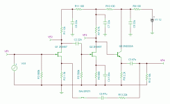
This is the schematic for said preamp. It will run off a DC line and fit inside an Altoids' tin. My reason for this decision is because I saw a blog where someone built a Cmoy amplifier and encased it in clear resin. He built it without a circuit board or tag strips and it inspired me to learn different construction methods. I played around with the design in TINA-TI for an evening before coming up with a design I liked.

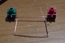
This is the "skeleton" of the preamp so far. The heavy copper wire is a ground bus (ground loop? 😛) and the I/O jacks. I also intend to include 10K linear pots as volume controls (one for each channel). I know there are audio pots as well but I think the 5K input impedance (approx.) of the power amp will change the resistance curve to be a little more toward the log side. If not, I can solder a 4K7 resistor between the wiper and the ground end. The skeleton measures 1.5" by 1.75" roughly and all of those components have to go into it.

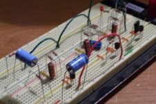
This is the breadboard with the amplifier being tested. Note that, despite all the components, this is just one channel. It seems that it will be gigantic pain but I will probably be happy with the result once it is completed.
I will post more pictures when I am farther along.
Ed
Last week I thought I was having soldering problems. It turned out to be a bad tube of solder I obtained from Wal-Mart. Don't buy solder from there...
Anyway, to confirm that I had a good technique and it was the solder, I started what I hoped would be a one-day project. Well, it wasn't. I am trying to design a line-level preamp to boost the signal out from maybe around 0.3v to 1-2vrms. This revolves around my decision to under-power the gain of my power amplifiers, making them dependent on a preamp for full-power. This is for various reasons.

This is the schematic for said preamp. It will run off a DC line and fit inside an Altoids' tin. My reason for this decision is because I saw a blog where someone built a Cmoy amplifier and encased it in clear resin. He built it without a circuit board or tag strips and it inspired me to learn different construction methods. I played around with the design in TINA-TI for an evening before coming up with a design I liked.

This is the "skeleton" of the preamp so far. The heavy copper wire is a ground bus (ground loop? 😛) and the I/O jacks. I also intend to include 10K linear pots as volume controls (one for each channel). I know there are audio pots as well but I think the 5K input impedance (approx.) of the power amp will change the resistance curve to be a little more toward the log side. If not, I can solder a 4K7 resistor between the wiper and the ground end. The skeleton measures 1.5" by 1.75" roughly and all of those components have to go into it.

This is the breadboard with the amplifier being tested. Note that, despite all the components, this is just one channel. It seems that it will be gigantic pain but I will probably be happy with the result once it is completed.
I will post more pictures when I am farther along.
Ed
You might also want to check out this thread - http://www.diyaudio.com/forums/solid-state/54333-jfet-cascade-line-amp.html . I wasn't too satisfied with the sound of the preamp at the time, but I might try a listen (and a measure) again some time, as my system has changed and the board is still floating around somewhere in the basement.
That's pretty interesting. You certainly gave 110% in the power supply regulation. It seemed like some of the posters were bothered by your design because it was different from the way they design preamps. Interesting how audio people work, hm?
My power amp sounds nice and loud, even though I lowered the gain with generous NFB. It may even curtail the use of a preamp. I still want to go ahead with the design so I can get experience making them. I was using a 12AU7/IRF510 headphone amp as the preamp for a little while but it actually clipped because of its relatively low headroom. I want to try and build many things and sometimes I build a headphone amp to try out a technique I'd like to use in a power amp. I've yet to design a through-and-through DC coupled amp.
At the same time, I haven't heard problems with coupling capacitors that some people decry. My stereo (all transistor, 5w out) uses electrolytic coupling caps and it sounds like any tube amp I've built or any stereo receiver I've heard. If you make the cap large enough, there won't be enough voltage developed across it for it to contribute to distortion. You just can't use small electros that eat up significant signal at the low end.
As for coupling caps, I normally like to use the green mylar caps where I can. Sometimes the impedances are so low that I have to use a 10uF electro. As mentioned before, it doesn't bother me.
Ed
I use polypropylene, polycarbonate, and polystyrene coupling caps, depending what I can scrounge and how much capacitance is needed. There are still some good deals on Ebay (especially the Russian polystyrenes), and I'm blessed with some local surplus stores that have an excellent selection of high quality film caps. The green mylar "chiclets" are a little bit too grubby for my taste - they may be inductive as well, depending on their manner of construction.
BTW, the only thing I don't like about nailing the feedback resistor on the other side of the coupling cap is the DC bias it can present to the outside world - a disaster for some piece of gear that has a DC coupled input. This would not be a big deal for a power amp, but a cause of concern for a preamp/line driver.
BTW, the only thing I don't like about nailing the feedback resistor on the other side of the coupling cap is the DC bias it can present to the outside world - a disaster for some piece of gear that has a DC coupled input. This would not be a big deal for a power amp, but a cause of concern for a preamp/line driver.
BTW, the only thing I don't like about nailing the feedback resistor on the other side of the coupling cap is the DC bias it can present to the outside world - a disaster for some piece of gear that has a DC coupled input. This would not be a big deal for a power amp, but a cause of concern for a preamp/line driver.
There is a capacitor to block the DC from the output back into the input. The output of a piece of gear should be at 0v. If it is not, it may upset the bias of the first JFET. The first JFET is not DC-coupled to any other stages so it wouldn't pass the error on. That is why I like capacitors in the circuit. Yes, you can do it the other way but you open yourself up to more problems.
I do want to learn how to design stable all-DC amps but capacitors help when all you want is a simple circuit. Plus, DC coupling is almost impossible to do with tubes. Almost.
Ed
I missed your second capacitor in the feedback chain. Some would carp ( people always carp) about two caps in series... As a side note, neither C3 nor C5 really needs to be 47uF.
At any rate, I've been looking at this problem for a few years, as doing a low gain preamp like this with a simple discrete circuit is one of the hardest things one can do, combining large signal swing, low distortion, low gain, and proper centering with respect to the available Vcc. If you search for my user name in solid state and analog line level, you'll see several threads that address the problem - I'm too lazy to pick them out. The one I showed you (check the date), was the very first in a series. Before that thread, I was using a unity gain buffer - relatively easy, though there are many ways to skin that particular cat. The preamp in my living room system to date is based on my "Liniac Revisited" thread. I'm working on another one right now based on synthesizing something that looks like a SIT using a mosfet with feedback.
At any rate, I've been looking at this problem for a few years, as doing a low gain preamp like this with a simple discrete circuit is one of the hardest things one can do, combining large signal swing, low distortion, low gain, and proper centering with respect to the available Vcc. If you search for my user name in solid state and analog line level, you'll see several threads that address the problem - I'm too lazy to pick them out. The one I showed you (check the date), was the very first in a series. Before that thread, I was using a unity gain buffer - relatively easy, though there are many ways to skin that particular cat. The preamp in my living room system to date is based on my "Liniac Revisited" thread. I'm working on another one right now based on synthesizing something that looks like a SIT using a mosfet with feedback.
They are electrolytic caps anyway (as if I could fit a non-electrolytic, 47uF cap into an Altoids' tin). If I were trying to go for the gold I would have done a much better design and taken more time in deciding the layout. Because I haven't, it clearly shows.
The intent of this amplifier is to get a taste for making one of its kind. I'm not making it as a prototype for a production run or to please an audiophile willing to shell out $10,000 for the magical little can. I haven't done too much in the preamp universe and if I were serious, I would incorporate a stepped attenuator, several selectable inputs, the obligatory optional phono stage, and maybe a display. None of these things fit within the small tin.
I'm not going to debate that there are better ways to do this. I'm just getting my feet wet in a new pool and wanted to try something I can understand before wading toward the deep end. I appreciate your help. So far you've approached this with an air of helpfulness instead of trying to pee in the pool. Please don't pee in the pool.
Ed
I don't doubt you'll get some sounds out of the preamp - I did with a similar circuit seven years ago. I shut mine down after ~1/2 hr and went back to the drawing board due to severe listener fatigue - it measured OK, but it just didn't sound right. Your experience may be different - let us know either way.
You have me curious enough that I might try to dig up my old boards and listen to them again to see if changes I've made in the system since then have altered the sound for the better.
I would suggest nice electrolytics if you're going to use them in the signal path. I used low-ESR caps like UCC LXZ/KZE or Panasonic HFQ/FC/FM. Others swear by the Elna Slimics, which are available from Digi-key. Paralling a 1-10 uF film cap across each electrolytic might be a good thing to try once you're settled in with the preamp.
If you try this and get tired of it, check out some of the other threads I mentioned. I'm getting good sounds from designs not much more complicated than this one. I also give 250% to the power regulation these days - that series pass design on my old cascade amp has been replaced by a fancy-pants high bandwidth shunt regulator.
- Status
- Not open for further replies.
- Home
- Source & Line
- Analog Line Level
- Line Level Preamp, Using JFETs, in a can.