Hi,
over the last three years, I read a lot in several forums, posted questions and build several phono pre's or parts of it and simulated some pre's as well.
There is a lot of debate of low noise, good psu, riaa network accuracy or the best sounding active device. There are two issues, though, that are crucial for an outstanding performance, but are not that often discussed.
I'm talking about best ways to acutally drive a riaa network (which amount of current/slew rate do you need, should the voltage swing over the network be small or huge etc.) from a technical perspective.
But that would be my #2.
For now, I'm interested in a high gain device. Compared to the attention that people pay to a preamp that has a gain of max. 12dB this is surprsingly seldom discussed.
And if your heading for a low distortion AND open loop design, you're on your own.
People talk about the best sounding buffers, but does acutally happen if your toss an AD797 in your circuit with say 50dB gain (that may have to drive the riaa net as well)?
Given the highly regarded sk170 and the like fets, what is your favorite high gain building block?
I'm about to finish two different first stage approaches for which I have high hopes, so my main concern is the second stage in a phono pre (MC) or the first for MM.
I'm aware of the more often discussed phono pres here, but maybe there's thread that slipped me which discusses my concern
Your question hides a lot of assumptions.
Before you choose an active device, you need to pick on a design topology.
There at least the following, which have been used:
1) Single gain block, EQ set in FB network.
2) Two gain blocks (second could be unity, but need not), with passive network between them.
3) Two gain blocks with passive HF between, but active FB setting LF on second.
4) Three gain blocks (well the last was a buffer), with passive EQ split between them - used in a valve design.
In principle, some of the EQ could be implemented in the FB network of the first stage of a multi-block design, but I can't bring an example of that to mind.
Note that multiple gain block designs ease the problem of getting high gain from one stage.
The other big issue is what type of cartridge you are designing for - as MC and MM are quite different challenges.
Hi,
let's assume the following:
- MC Cartridge
- first stage is present & runs at 30dB @1kHz
- is dc-coupled (with the aid of a servo) at the output
- This stage has the 2.21kHz roll-off implemented (passive)
- the whole amp may have 2 or 3 stages
- should be open loop, if at last possible. However, open loops specs should be close to what we need in the end, in terms of distortion and bandwith
- second part riaa may be active or passive
- a solid state discrete design.
- shall make use of the 2sk389/2sj109 gems I have lying around, unless there is a real good reason not to use them.
- complexity no object, IF it helps.
Rüdiger
You might want to check this out - should answer some of these questions.
http://www.klaus-boening.de/
http://www.klaus-boening.de/
Hi Hanginon,
in fact, I already build this circuit. It sounds good, but I have issues with it. One is, that with all this batteries you get complicated current loops. A second is, that the first stage has to feed rather big riaa caps, A third is, you have coupling caps and an output trafo. Fourth, the gain needed in the compound stage is substantial, and its tough to make it behave well.
Rüdiger
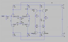
Rüdiger, have you seen my QSXM2 monster? The input stage be be fitted with MAT02/03 or JFET's. Lot's of tweak potential.
The basic idea is a non-inverting preamp + inverting RIAA stage.
The basic idea is a non-inverting preamp + inverting RIAA stage.
Hi P-A,
now we are talking!
I've probably seen it some years ago but did not understand. It seems I make at least slow progress, as I understand some things now...
For now, I'm referring to schematic2.
- You use a current source that feeds the cascode (T43, T45). I thought, that you need a low impedance at the base here. Am I wrong?
- What exactly is T49 doing and how does it work?
Rüdiger
(Sideline information: )
Also used in the Hagtech Bugle:
http://www.hagtech.com/images/bugleschem.gif
(back to the thread...)
PigletsDad said:
...
4) Three gain blocks (well the last was a buffer), with passive EQ split between them - used in a valve design.
Also used in the Hagtech Bugle:
http://www.hagtech.com/images/bugleschem.gif
(back to the thread...)
It's a plain cascode, increasing the speed, lowering the distortion.Onvinyl said:- You use a current source that feeds the cascode (T43, T45). I thought, that you need a low impedance at the base here. Am I wrong?
It's an emitter follower, less capacitve load to the first stage => increased speedOnvinyl said:- What exactly is T49 doing and how does it work?
peranders said:It's a plain cascode, increasing the speed, lowering the distortion.
That's the piece I know. What I don't know is the advantage of biasing the cascodes base with a high impedance via a CCS.
Rüdiger
You want the voltage to be floating between the emitters of the input transistors and the emitters of the upper cascode transistors. A big cap + a high resistor value forms a floating voltage.
- Status
- Not open for further replies.
- Home
- Source & Line
- Analog Line Level
- Designing a phono pre. #1: high gain block