Hi,
I am new to this forum. Maybe you can help me with my power- amplifier
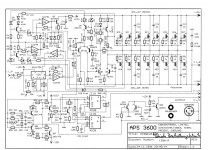
Zoffmusic APS3600.
I got this one as a “present” from a friend of mine, in very bad rusty, defect condition.
Many mosfets in both channels died.

I managed to get one channel working, using the surviving 2SK2221 and 2SJ352 mosfets,
collected from both channels, and it works perfect. I get full 1000Watt power, and the sinewave is perfect. Tested from 30Hz to 25KHz.
For the other channel I bought
Exicon ECX10P20 as a replacement for the 2SK2221
Exicon ECX10N20 as a replacement for the 2SJ352
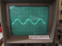
It basically works with them, but I have a problem with „transients“ showing up on the falling edge of the positive half- wave of the output signal.

I had adjusted the standby- current to 150mA for each rail: The positive and negative supply.
I know this is small, but I had measured this current on the working channel that uses the surviving 2SK2221 and 2SJ352 mosfets.
I already swapped the control boards, to exclude a defect from them. But the result is the same:
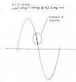
Transients of about 400KHz showing up on the test output- signal (falling edge) on the channel equipped with the new mosfets.
I first started with a test sine- wave of 1KHz and I had this issue.
Then I increased the silence- current a bit and was able to make the transients disappear. 🙂
When I set the test sine wave from 5KHz up to 20KHz the transients come back :-(
By further increasing the silence current up to 800mA per rail (100mA per mosfet) I am able to move the transient package in the area of the zero- crossing of the oscillogram. But it can not make it disappear again. And of cause then the mosfets / heatsink becomes hot very quickly.
Do you have any ideas what should be changed in the driving circurit to get it perfectly working with these Exicon mosfets?
Things I allready tried:
- Grounding the heatsink
- Soldering 33pF ceramic capacitors like C11 to C 16 between positive power
supply and each gate of each 10P20
and also between negative power supply and each gate of each 10N20.
Like shown in the schematic, but one capacitor for each mosfet now.
But it did not help. 🙁
If you could help me with this, it would be great.
Thank you very much in advance.
Best regards,
Christian
I am new to this forum. Maybe you can help me with my power- amplifier
Zoffmusic APS3600.
I got this one as a “present” from a friend of mine, in very bad rusty, defect condition.
Many mosfets in both channels died.
I managed to get one channel working, using the surviving 2SK2221 and 2SJ352 mosfets,
collected from both channels, and it works perfect. I get full 1000Watt power, and the sinewave is perfect. Tested from 30Hz to 25KHz.
For the other channel I bought
Exicon ECX10P20 as a replacement for the 2SK2221
Exicon ECX10N20 as a replacement for the 2SJ352
It basically works with them, but I have a problem with „transients“ showing up on the falling edge of the positive half- wave of the output signal.
I had adjusted the standby- current to 150mA for each rail: The positive and negative supply.
I know this is small, but I had measured this current on the working channel that uses the surviving 2SK2221 and 2SJ352 mosfets.
I already swapped the control boards, to exclude a defect from them. But the result is the same:
Transients of about 400KHz showing up on the test output- signal (falling edge) on the channel equipped with the new mosfets.
I first started with a test sine- wave of 1KHz and I had this issue.
Then I increased the silence- current a bit and was able to make the transients disappear. 🙂
When I set the test sine wave from 5KHz up to 20KHz the transients come back :-(
By further increasing the silence current up to 800mA per rail (100mA per mosfet) I am able to move the transient package in the area of the zero- crossing of the oscillogram. But it can not make it disappear again. And of cause then the mosfets / heatsink becomes hot very quickly.
Do you have any ideas what should be changed in the driving circurit to get it perfectly working with these Exicon mosfets?
Things I allready tried:
- Grounding the heatsink
- Soldering 33pF ceramic capacitors like C11 to C 16 between positive power
supply and each gate of each 10P20
and also between negative power supply and each gate of each 10N20.
Like shown in the schematic, but one capacitor for each mosfet now.
But it did not help. 🙁
If you could help me with this, it would be great.
Thank you very much in advance.
Best regards,
Christian
Attachments
What you have is basically a more modern version of mosfet than the original ones , this comes with a much reduced input capacitance from 800pf to 500pf , of course class A can "cure " many small oscillations but isn't a complete cure as its potentially unstable --not by a lot but enough to show up on a sine/square wave .
This isnt a big problem and should be easily cured but upping the COMPENSATION capacitor (s) till it disappears, try upping --C9 & C10 --not by a lot watching it on your scope till it disappears--then slightly more for stability and safety .
We are not talking a big increase just a small one , when building power amps to your own design this is typical behavior for me as I don't use any virtual helpers /programmes just do it the old fashioned way and its never let me down.
If that doesn't work get back but it should, again this shows what I always say old amplifier designs used the active devices available at the time "improving" an old design while not making other changes to the circuit can leave you with even worse than you have , it shows the original good stability of the design that that is all that's occurred.
Thank you for yor reply Duncan.
First I must say I made a mistake with my dummy- load. It was 16ohms when I measured first and posted the oscillgram.
Now I fixed it to 8ohms and things become even worse.
I found with no load, the output sine wave is absolutely perfect.
I can adjust the generator from 50Hz to 20KHz and all levels of amplitude the amp will give a good clean output signal.
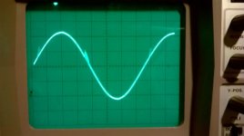
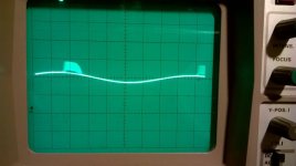
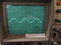
When I now hook the 8ohm dummy to it, at very low input level (~30watt at the output) the sine wave is ok:

50V / Div
If I increase the input level, the oscillation on the positive sine- half- wave shows up:

50V / Div
This oscillation is about 400KHz
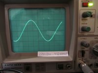
When I further increase the input signal, the oscillation establishes more:

50V / Div
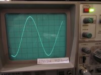
Further increased input signal. Output ~ 80Vpp:

50V / Div
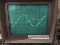
At about 100Volt peak/peak the oscillation breaks up into two pieces:

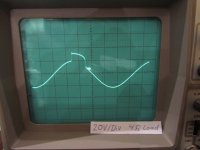
At about 170 Volts peak / peak the transients of the oscillation become smaler

At 250Volt peak / peak = Full 1000watt Power the transients habe become rather small:

Today I tried the following things:
- Different values for C9 and C10, like suggested:
10pF, 15pF (original), 18pF, 22pF, 33pF, 47pF. The result is still the same:
400Khz ocillations on the output signal.
The only way to dampen them, is to increase the silence current of the output
mosfets, which of cause results in a quick heat up of the putput mosfests.
- Added some capacitors to the controll- board, to extra buffer the +/- voltage-
supply in the area of the driver stage: 4.7uF and 0.1uF extra.
- Tried again capacitors from gate to V+ and gate to V- like C11 to C16.
But this time 150pF on every Mosfet
Without luck 🙁
Does anybody see further parts of the driver circuit, that could be adapted /
modified, to make them work with these Exicon Mosfets?
Or does anyone know an actual power amplifier, in the 1000watt range,
that works with 8pcs. ECX10N20 and 8pcs. ECX10P20 Mosfets and +/- 125Volts Power supply? Maybe I can get some ideas, what has to be changed.
Thank you very much in advance.
Best regards,
Christian
First I must say I made a mistake with my dummy- load. It was 16ohms when I measured first and posted the oscillgram.
Now I fixed it to 8ohms and things become even worse.
I found with no load, the output sine wave is absolutely perfect.
I can adjust the generator from 50Hz to 20KHz and all levels of amplitude the amp will give a good clean output signal.
When I now hook the 8ohm dummy to it, at very low input level (~30watt at the output) the sine wave is ok:
50V / Div
If I increase the input level, the oscillation on the positive sine- half- wave shows up:
50V / Div
This oscillation is about 400KHz
When I further increase the input signal, the oscillation establishes more:
50V / Div
Further increased input signal. Output ~ 80Vpp:
50V / Div
At about 100Volt peak/peak the oscillation breaks up into two pieces:
At about 170 Volts peak / peak the transients of the oscillation become smaler
At 250Volt peak / peak = Full 1000watt Power the transients habe become rather small:
Today I tried the following things:
- Different values for C9 and C10, like suggested:
10pF, 15pF (original), 18pF, 22pF, 33pF, 47pF. The result is still the same:
400Khz ocillations on the output signal.
The only way to dampen them, is to increase the silence current of the output
mosfets, which of cause results in a quick heat up of the putput mosfests.
- Added some capacitors to the controll- board, to extra buffer the +/- voltage-
supply in the area of the driver stage: 4.7uF and 0.1uF extra.
- Tried again capacitors from gate to V+ and gate to V- like C11 to C16.
But this time 150pF on every Mosfet
Without luck 🙁
Does anybody see further parts of the driver circuit, that could be adapted /
modified, to make them work with these Exicon Mosfets?
Or does anyone know an actual power amplifier, in the 1000watt range,
that works with 8pcs. ECX10N20 and 8pcs. ECX10P20 Mosfets and +/- 125Volts Power supply? Maybe I can get some ideas, what has to be changed.
Thank you very much in advance.
Best regards,
Christian
Attachments


Last edited:
You could try a small cap across the feedback resistor R25 (22pF). Or/and a 100pF cap across R27. Input capacitance of NFET is less than PFET. Ideally the gate resistors should be greater for NFET than PFET. Increasing NFET side to 1.5K may help. The oscillations ahow that there is too much bandwidth on the NFET side.
HF oscillation is more likely to happen in paralleled mosfets , I am not saying it happens all the time only its MORE likely to happen .
If the gain of the replacement mosfets is higher than the originals that too can cause oscillation also small circuit changes can also cause it .
I am not a follower of this but I notice many are ,you can try putting a small ferrite bead inline with the gate resistors to see if that cures it .
It would cure HF oscillations in the MHz range but at 400KHz that's another thing . I notice the FT of the original mosfets starts dropping before 400KHz .
Trying to improve it, but little success
Hello Duncan, Spladski,
thank you for your replies.
In the meantime I contacted Exicon for some information, how they would design a 1000watts / 4Ohm amplifier using their ECX10N20 and ECX10P20 mosfets.
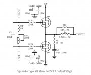
-Unfortunately without success, but they send me an application note on their lateral mosfets, which contains this sample output- stage:

Spladski, you where right about the gate resistors. It is stated in the application note, that the gate- resistors of the N-channel mosfet should be of higher value,
than the gate resistor of the P-channel mosfet.
They also state, that when mosfets are paralleled:
- oscillations can occur, and to avoid this, a 470pF cap should be connected from
gate to source and as close as possible to the mosfet.
They also state, that the buffer- capacitors of the power- rails should be placed as close as possible to the the mosfet, to make the circuit more stable.
And I also saw this on the amplifier boards available at holton precision audio.
Given this info, my schematic is now looking like this:

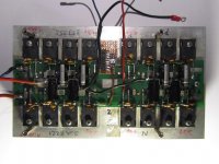
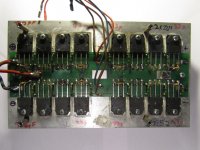
Here is a picture how the heatsink - mosfet output stage looks, with original 2SK2221 / 2SJ352:

Here is the modified channel, now equipped with
-ECX10N20 and ECX10P20
As close as possible to the mosfets:
-extra buffer capacitors 4 pcs. 47uF / 160V + 4 pcs. 100nF for each rail
-470pF cap from gate to source on every mosfet
-33pf cap from gate to drain on every mosfet
-1.5K Ohm gate resistors for the N-channel mosfets
-shortened the gate- controll wires (antennas) from controll- pcb to output-stage pcb / heatsink as short as possible by using a connector and socket.

All parts connected as close as possible to the mosfet:

I was very curious, when I powered up the amplifier again with these modifications.
In their application- note, Exicon states that the ECX10N20 and ECX10P20 are ideally biased to a silence- current of 200mA per mosfet.
For high- power applications like my amplifier they should still work reliable with a silence- current of 50mA.
So I adjusted the silence current to 400mA for each (8 x 50mA) - positive and negative rail.
For a first test, I set the output power to 18watts @ 4 ohms:

The first scope shot looked promising...
I increased the power to 30watts @ 4ohms:

Again something bad took its place on the top of the positive sine- halfwave.
My scope had trouble to trigger it 😱
I further increased the power to 60watts @ 4ohms:

The over- shoot on top manifested more and more.
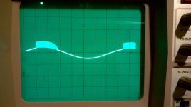
But this time the fault looks different then in my last post:
The 400Khz oscillation has disappered, but its "frame" is still left (empty) on top of the positive sine halfwave. 😕
I further increased the output power to 125watts @ 4ohms:

Now the over- shoot becomes smaller, in relation to the wanted signal.
I further increased the output- power to 200watts @ 4ohms:

Now the signal is clean again.
I further increased the power to 600watts @ 4ohms:

The signal stays clean...
I further increased the output power to maximum 1250watts @ 4ohms:

The visible signal stays clean.
Temporary result:
It seems that the modifications / added capacitors stabilize the circuit and improve it to a certain degree.
When I raise the bias silence- current to values of ~ 175mA per mosfet,
= ~ 1400mA per rail, the overshoot disappeares completely.
175mA (200mA) per mosfet could be ok, like stated in the application note / datasheet,
but in my case, in an amplifier operating with +/- 125volts rail voltage this results in an unwanted big heat generation.
If anybody out there knows a better way ho to drive these mosfets or what could be further improved in the driver circuit, to get rid of this shark- fin, on top of the sine wave, at low power levels, please let me know.
Thank you very much in advance and
best regards
Christian
Hello Duncan, Spladski,
thank you for your replies.
In the meantime I contacted Exicon for some information, how they would design a 1000watts / 4Ohm amplifier using their ECX10N20 and ECX10P20 mosfets.
-Unfortunately without success, but they send me an application note on their lateral mosfets, which contains this sample output- stage:
Spladski, you where right about the gate resistors. It is stated in the application note, that the gate- resistors of the N-channel mosfet should be of higher value,
than the gate resistor of the P-channel mosfet.
They also state, that when mosfets are paralleled:
- oscillations can occur, and to avoid this, a 470pF cap should be connected from
gate to source and as close as possible to the mosfet.
They also state, that the buffer- capacitors of the power- rails should be placed as close as possible to the the mosfet, to make the circuit more stable.
And I also saw this on the amplifier boards available at holton precision audio.
Given this info, my schematic is now looking like this:
Here is a picture how the heatsink - mosfet output stage looks, with original 2SK2221 / 2SJ352:
Here is the modified channel, now equipped with
-ECX10N20 and ECX10P20
As close as possible to the mosfets:
-extra buffer capacitors 4 pcs. 47uF / 160V + 4 pcs. 100nF for each rail
-470pF cap from gate to source on every mosfet
-33pf cap from gate to drain on every mosfet
-1.5K Ohm gate resistors for the N-channel mosfets
-shortened the gate- controll wires (antennas) from controll- pcb to output-stage pcb / heatsink as short as possible by using a connector and socket.
All parts connected as close as possible to the mosfet:
I was very curious, when I powered up the amplifier again with these modifications.
In their application- note, Exicon states that the ECX10N20 and ECX10P20 are ideally biased to a silence- current of 200mA per mosfet.
For high- power applications like my amplifier they should still work reliable with a silence- current of 50mA.
So I adjusted the silence current to 400mA for each (8 x 50mA) - positive and negative rail.
For a first test, I set the output power to 18watts @ 4 ohms:
The first scope shot looked promising...
I increased the power to 30watts @ 4ohms:
Again something bad took its place on the top of the positive sine- halfwave.
My scope had trouble to trigger it 😱
I further increased the power to 60watts @ 4ohms:
The over- shoot on top manifested more and more.
But this time the fault looks different then in my last post:
The 400Khz oscillation has disappered, but its "frame" is still left (empty) on top of the positive sine halfwave. 😕
I further increased the output power to 125watts @ 4ohms:
Now the over- shoot becomes smaller, in relation to the wanted signal.
I further increased the output- power to 200watts @ 4ohms:
Now the signal is clean again.
I further increased the power to 600watts @ 4ohms:
The signal stays clean...
I further increased the output power to maximum 1250watts @ 4ohms:
The visible signal stays clean.
Temporary result:
It seems that the modifications / added capacitors stabilize the circuit and improve it to a certain degree.
When I raise the bias silence- current to values of ~ 175mA per mosfet,
= ~ 1400mA per rail, the overshoot disappeares completely.
175mA (200mA) per mosfet could be ok, like stated in the application note / datasheet,
but in my case, in an amplifier operating with +/- 125volts rail voltage this results in an unwanted big heat generation.
If anybody out there knows a better way ho to drive these mosfets or what could be further improved in the driver circuit, to get rid of this shark- fin, on top of the sine wave, at low power levels, please let me know.
Thank you very much in advance and
best regards
Christian
Attachments

Have you played around with different gate resistor values?
The Exicon parts have a different requirement than the older parts that they are made to replace, although I would think 1k ohm should be ok.
There’s an application guide on the Profusion website that could maybe be helpful.
Also I always try and put a tiny ferrite on the gate leads of laterals, as close as possible.
Again my message, this time with pictures...
Hello Duncan, Spladski,
thank you for your replies.
In the meantime I contacted Exicon for some information, how they would design a 1000watts / 4Ohm amplifier using their ECX10N20 and ECX10P20 mosfets.
-Unfortunately without success, but they send me an application note on their lateral mosfets, which contains this sample output- stage:

Spladski, you where right about the gate resistors. It is stated in the application note, that the gate- resistors of the N-channel mosfet should be of higher value,
than the gate resistor of the P-channel mosfet.
They also state, that when mosfets are paralleled:
- oscillations can occur, and to avoid this, a 470pF cap should be connected from
gate to source and as close as possible to the mosfet.
They also state, that the buffer- capacitors of the power- rails should be placed as close as possible to the the mosfet, to make the circuit more stable.
And I also saw this on the amplifier boards available at holton precision audio.
Given this info, my schematic is now looking like this:

Here is a picture how the heatsink - mosfet output stage looks, with original 2SK2221 / 2SJ352:

Here is the modified channel, now equipped with
-ECX10N20 and ECX10P20
As close as possible to the mosfets:
-extra buffer capacitors 4 pcs. 47uF / 160V + 4 pcs. 100nF for each rail
-470pF cap from gate to source on every mosfet
-33pf cap from gate to drain on every mosfet
-1.5K Ohm gate resistors for the N-channel mosfets
-shortened the gate- controll wires (antennas) from controll- pcb to output-stage pcb / heatsink as short as possible by using a connector and socket.

All parts connected as close as possible to the mosfet:

Best regards,
Christian
Hello Duncan, Spladski,
thank you for your replies.
In the meantime I contacted Exicon for some information, how they would design a 1000watts / 4Ohm amplifier using their ECX10N20 and ECX10P20 mosfets.
-Unfortunately without success, but they send me an application note on their lateral mosfets, which contains this sample output- stage:
Spladski, you where right about the gate resistors. It is stated in the application note, that the gate- resistors of the N-channel mosfet should be of higher value,
than the gate resistor of the P-channel mosfet.
They also state, that when mosfets are paralleled:
- oscillations can occur, and to avoid this, a 470pF cap should be connected from
gate to source and as close as possible to the mosfet.
They also state, that the buffer- capacitors of the power- rails should be placed as close as possible to the the mosfet, to make the circuit more stable.
And I also saw this on the amplifier boards available at holton precision audio.
Given this info, my schematic is now looking like this:
Here is a picture how the heatsink - mosfet output stage looks, with original 2SK2221 / 2SJ352:
Here is the modified channel, now equipped with
-ECX10N20 and ECX10P20
As close as possible to the mosfets:
-extra buffer capacitors 4 pcs. 47uF / 160V + 4 pcs. 100nF for each rail
-470pF cap from gate to source on every mosfet
-33pf cap from gate to drain on every mosfet
-1.5K Ohm gate resistors for the N-channel mosfets
-shortened the gate- controll wires (antennas) from controll- pcb to output-stage pcb / heatsink as short as possible by using a connector and socket.
All parts connected as close as possible to the mosfet:
Best regards,
Christian
Attachments

Gate resistors, ferrite beads...
Hello Phase,
like forum member Spladski suggested, I have increased the gate- resistors for the N-channel mosfets from 1k to 1.5k
Do you think I further have to increase them, to get rid of the "shark- fin" over- shoot on the sine wave signal?
I also read about the ferrite beads, to be put as close to the gate pin as possible.
Like you can see in pictures I have posted now, I extremely shorted the gate pins and soldered the ceramic caps and gate resistors to the remaining pin.
I also read in the application note, that ferrite beads are used to eliminate oscillations
in the MHz range.
Before I made my actuall modifications I had problems with oscillations around
400KHz.
So I thought ferrite beads would not help me.
Do you have other experience?
The thing ist, when the amplifier is cold and I turn it on, the signal distortion is stronger. It occures allready at small output signals.
When the heat sink warms up, from silence current, the signal distortion becomes smaller.
Like I wrote, I can adjust the silence current to 150 up to 200mA per mosfet.
The amplifier then works OK, and the overshoot disappeares completely.
175mA (200mA) per mosfet could be ok, like stated in the application note / datasheet,
but in my case, in an amplifier operating with +/- 125volts rail voltage this results in an unwanted big heat generation.
And also because I now have installed the new elctrolytic capacitors to the mosfet / heatsink unit, I would like to have it more cool, to protect the capacitors from unneccessary heat.
Another observation is that if I connect a higher resistance load, like 16 ohms to the amplifier, there is nearly no over- shoot visible.
With 8 ohms they are visible and the lower the load resistance becomes, like 4ohms they more and more manifest.
Best regards,
Christian
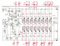
C9 and 10 are too small.
The circuit is strange with small caps on some gates but not others.
Its basically the Hitachi datasheet circuit with many mosfets on the output instead of a single pair.
The 1K gate resistors are usually 100R-390R. You could be getting delayed on/off times due to this.
The circuit is strange with small caps on some gates but not others.
Its basically the Hitachi datasheet circuit with many mosfets on the output instead of a single pair.
The 1K gate resistors are usually 100R-390R. You could be getting delayed on/off times due to this.
Hello Nigelwright,
thank you for your answer.
I allready increased C9 and 10 to 25pF.
Forum member duncan mentioned this eralier. I tried different values from 10pF up to 100pF with little or no success.
Please look at my actual circuit diagramm.
I now have added 33pF gate / drain and 470pF gate / source to every mosfet.
Do you think I should decrease the gate resistors to 330R for the N-channel and 220R for the P-channel?
Actually I have 1.5k for the N-channel and 1k for the P-channel.
I thought, the values might be double the values of the sample hitachi circuit because of the high rail- voltage +/- 125V ?
Best regards,
Christian
Last edited:
Hi Christian,
I know that parallel connected Exicon laterals can have RF stability problems unless they are very carefully matched. Perhaps the original mosfets in your amplifier were matched to prevent RF instability and achieve good current sharing between the mosfets. Assuming the Exicon laterals you used aren't matched I suggest putting a 0.22 Ohm, 7 Watt wire wound resistor in the source of every mosfet. Also the audio ac voltage across the resistor provides some negative feedback to improve stability. Adding these ballast resistors won't reduce the damping factor of the amplifier because they are within the global negative feedback loop. I have an amplifier that I built some years ago with non-matched Exicon laterals in parallel. I have the 0.22 Ohm ballast resistors in the source of each mosfet and there are no instability problems.
I know that parallel connected Exicon laterals can have RF stability problems unless they are very carefully matched. Perhaps the original mosfets in your amplifier were matched to prevent RF instability and achieve good current sharing between the mosfets. Assuming the Exicon laterals you used aren't matched I suggest putting a 0.22 Ohm, 7 Watt wire wound resistor in the source of every mosfet. Also the audio ac voltage across the resistor provides some negative feedback to improve stability. Adding these ballast resistors won't reduce the damping factor of the amplifier because they are within the global negative feedback loop. I have an amplifier that I built some years ago with non-matched Exicon laterals in parallel. I have the 0.22 Ohm ballast resistors in the source of each mosfet and there are no instability problems.
I think it is working OK now...
Hi,
I was still busy with my Zoffmusic APS3600 during the last days.
But now I think it is working OK.
@ Chiefmegawatty:
Yes, I bought matched mosfets from exicon.
They offer them matched on a threshold voltage, resulting a current, available in six groups from 105mA up to 205mA. Each group color- coded.
With little knowledge about lateral mosfets, my amplifier and its problems and what I would need, I ordered them in the mid range,
selected on 140mA up to 155mA current, marked with a yellow dot.
This week, I first changed the gate- resistors from originally 1K to the given values of the sample- circuit shown in the application notes from Exicon:
330R for the N-channel mosfets ECX10N20
220R for the P-channel mosfets ECX10P20
The amplifier basically worked better with this combination, but runing the amplifier with a 2 ohm load, sometimes gave a spike, to positive / overshoot on the scope
and a loud "pop" from the speaker, when dynamic music was played and loud passages where in the song.
So I remembered that reducing the gate resistors helped me once and I reduced the gate resistors once more. This time to the low end given in the application note:
180R for the N-channel mosfets ECX10N20
100R for the P-channel mosfets ECX10P20
And surprice, this is how the amplifier actually works good for me,
even with low 2 ohm load, which I normally would not want to do. 😉
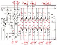
For all who also have to convert such an amplifier or similar, here is my actuall schematic:

All modifications are drawn in red.
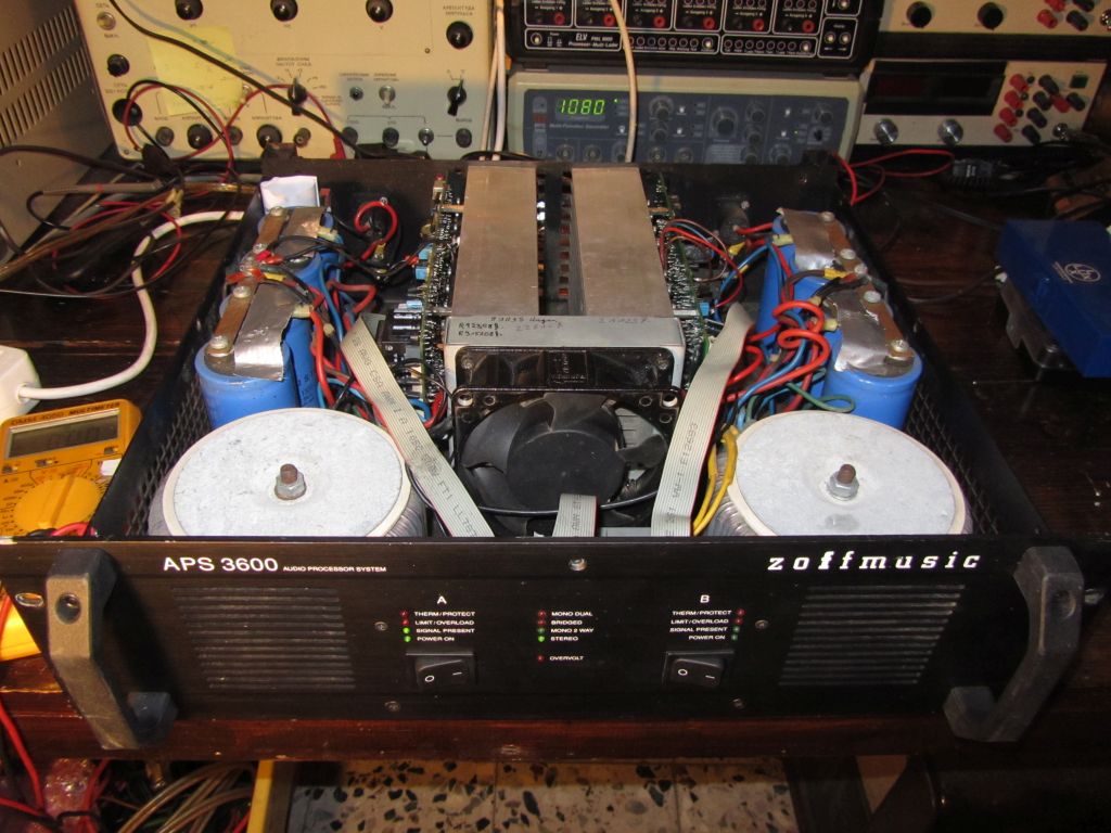
This is how the beast looks like:
So I thank you all very much:
Spladski, Duncan2, Phase, Nigelwirght, Chiefmegawatty,
for all the hints and ideas to get in the right direction, and make this amplifier working better.
Cheers,
Christian
Hi,
I was still busy with my Zoffmusic APS3600 during the last days.
But now I think it is working OK.
@ Chiefmegawatty:
Yes, I bought matched mosfets from exicon.
They offer them matched on a threshold voltage, resulting a current, available in six groups from 105mA up to 205mA. Each group color- coded.
With little knowledge about lateral mosfets, my amplifier and its problems and what I would need, I ordered them in the mid range,
selected on 140mA up to 155mA current, marked with a yellow dot.
This week, I first changed the gate- resistors from originally 1K to the given values of the sample- circuit shown in the application notes from Exicon:
330R for the N-channel mosfets ECX10N20
220R for the P-channel mosfets ECX10P20
The amplifier basically worked better with this combination, but runing the amplifier with a 2 ohm load, sometimes gave a spike, to positive / overshoot on the scope
and a loud "pop" from the speaker, when dynamic music was played and loud passages where in the song.
So I remembered that reducing the gate resistors helped me once and I reduced the gate resistors once more. This time to the low end given in the application note:
180R for the N-channel mosfets ECX10N20
100R for the P-channel mosfets ECX10P20
And surprice, this is how the amplifier actually works good for me,
even with low 2 ohm load, which I normally would not want to do. 😉
For all who also have to convert such an amplifier or similar, here is my actuall schematic:
All modifications are drawn in red.
This is how the beast looks like:
So I thank you all very much:
Spladski, Duncan2, Phase, Nigelwirght, Chiefmegawatty,
for all the hints and ideas to get in the right direction, and make this amplifier working better.
Cheers,
Christian
Attachments

- Home
- Amplifiers
- Solid State
- Zoffmusic APS3600 converting 2SK2221 2SJ352 to Exicon ECX10P20 ECX10N20 problem