I saw a while back somewhere that a tricky way to keep the no load voltage under control when you power up a tube amp was to use a string of zeners and a resistor to put some load on the power supply until the tubes are warm to prevent exceeding the peak rating of the power supply caps.
Any issues with this?
About all I could find was that the temp coefficient of the zener diode cause the voltage rating to go up based on temp so it's somewhat inaccurate with temp. That's ok for this application I think.
Again the idea is not at all to regulate the voltage of the amps power supply, but to clamp it on start up.
Normally I don't like this type of hack and would use proper voltage ratings on the capacitors but with one of the projects and transformer combinations the no load is about 525vdc and I have 450wvdc caps (with 10% for surge puts them at just under 500v) so need something to keep things safe during start up. Once powered up B+ is below 450v.
Thinking of 5@ 91v (1n5948) 3watt zener diodes and a 5k resistor (will have to try some math to make enough load and not draw too much from the diodes).
As long as I'm below the voltage of the clamp by some margin am I OK with this Hack???
Thanks
Sandy
5k in series with the diodes ? That will limit the current the diodes can draw.
525-(91*5)/5000 is 14 ma and then only if the supply were 525 volts. Depending how stiff the supply is it might not be enough, it could easily creep over 450 vdc.
Could be a trial and error job and it seems a bit of an indeterminate method really.
(Unless it spoilt originality 😱 would it be bad form to suggest an active clamp. Using transistor do dahs. Your zeners and a constant current sink (two transistors, no high wattage resistors) that only conducts when the voltage exceeds the zener value is easy to do. The current draw would be zero up to the point the zener voltage is exceeded, then it would draw whatever current you designed into it)
I played around with some values on PSU-Designer with a load of about 5k and it drops the voltage to about 450vdc, not sure if in real world that is enough but seemed like a safe starting point.
On PSU-D with a 5K resistor it draws about 9ma of current at 450v. Unloaded in PSU-D (500k resistor) it's voltage is at about 525v which is what I'm seeing in real world unloaded, have not tried a 5k yet real world but I guess that's really an easy try will do it tonight if I can.
With a 5k resistor and 9ma of current seems like about 4 watts which is also in range for a 5w resistor, possibly even use smaller 1.3 watt zeners.
Not sure if I'm way out of line with my simple assumptions...
Thanks for the comments so far!
Sandy
I do not like very much the idea of dissipating power in silicon, but transistors can be combined with power resistors and zeners to get the best of the three worlds.
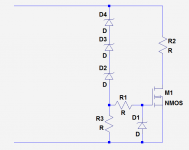
Here is what I mean: R1 and D1 just serve as a protection for the MOS (a MOS is practically unavoidable thanks to its ~square SOA)
D2 to 4 is your zener string, minus the Vth of the MOS (in principle negligible), R3 defines the current in the string, and R2 is the equivalent of your load, just a bit lower (in ohmic terms) to remain on the safe side. It will have to carry the brunt of the dissipation.
The MOS has to be rated for the maximum power to be dissipated in the load (in theory a quarter of that, but let's remain on the safe side), and it has to be bolted to a slab of metal (not actually an heatsink) having a sufficient thermal capacity for the whole duration of the "event".
Attachments
I've used both techniques (string of zeners, and power FET style zener) for choke input supplies - as the difference between start-up and idle voltage rail is much more than just a cap input supply. The concern with a string of zeners especially is that some may not appreciate the substantial derating needed for the zener device dissipation when simply soldered end-on-end. A "3 Watt" zener will only survive close to 3W (and that is for max junction tmp operation which should never really be approached in practise) if in 25C ambient with the requisite lead heatsinking. In practise, the leads provide effectively no heatsinking when soldered end-on-end. Similar to when a power FET device is used with no heatsinking as Elvee alerts, although this is managed in the shown example circuit by aiming to dissipate most of the load power in R2 (most people appreciate resistor power loss issues a bit better).
Last edited:
Some nice folks on here turned me onto the CL90 inrush current limiter when I was faced with the same dilemma, I haven't ordered any yet but plan on soon.
Not sure how the CL90 will help as I'm not having a problem with inrush, but with high voltage at start with a 5U4GB rectifier.
Here are some tests I just did -
with a 5k Ohm resistor and no load (no tubes) the power supply runs at 474 vdc, but as I quickly found out my calculation for power draw was way way off. It was drawing 90ma not 9ma 😱 so the power dissipation is 40 watts not 4 as I erroneously calculated. This error was brought to my attention via a smoking 10w resistor. Without the 5K resistor and with all tubes up and running hot plate voltage was 434v with the 5U4GB running cathode bias at about 20w per tube.
With a GZ34 the plate voltage bit on the high side (470v), but not so out of whack that I wouldn't think of using it. With the 5U4GB it was at a nice 434v on the plates but warm up is the problem.
I think the safe solution is to scrap the zener idea and replace a couple of the hv caps with the proper 500v models and even with the 525v cold start voltage it's well within the surge range of 550v, and if I do want to use a GZ34 these caps also will be fine.
Sometimes it seems the simple solution is to just do the right thing 🙂
Sandy
the thing i watch out for in my amps is exceeding the filter cap working voltage at any time.....i try to avoid that at all cost...
Not sure how the CL90 will help as I'm not having a problem with inrush, but with high voltage at start with a 5U4GB rectifier.
Yes, I have the same exact issue using the 5U4GB. I don't see how it could help now that I look at the datasheet, the CL90 has a cold resistance of 120R, this to me doesn't seem like it will increase the time constant worth a hoot. The CL90 would probably help in the inrush current charging the reservoir cap so you could probably increase it to a higher value, this is the only use I can see for the CL90, maybe someone will chime in and explain😕
Here is the quote form another thread about rectifier discussion.
BTW, if you want to slow the B+ rise down a bit when a directly heated vacuum rectifier is employed, install a CL-90 inrush current limiting thermistor between the rectifier and the PSU filter. FWIW, the presence of a CL-90 allows you to take a SMALL liberty in choosing the value of the 1st filter capacitor.
I wonder how long the delay on the CL-90 would be, it shows a cold resistance of 120 ohms and for some reason I'm going to guess other then softening the blow on cold charging the capacitors it's still going to have the same problem of over voltage until a load comes up from the tubes getting warmed up.
I think I solved the problem a better way, ordered the hard to find 500v caps and will put them in. Next design will go back to the pair of series 450v cap and be done with the hard to find 500v parts.
This is what I get for using left over transformers from other projects 🙂
Sandy
I think I solved the problem a better way, ordered the hard to find 500v caps and will put them in. Next design will go back to the pair of series 450v cap and be done with the hard to find 500v parts.
This is what I get for using left over transformers from other projects 🙂
Sandy
I soldered mine to a tag strip. Seems to work fine. The tags add some heat dissipation to each junction.trobbins said:The concern with a string of zeners especially is that some may not appreciate the substantial derating needed for the zener device dissipation when simply soldered end-on-end.
I had an receiver with a tube that visibly sparked every time I switched it on. It was a low voltage tube at the end of a long line of resistors supposed to operate at about 100V but usually got over 300V on switch on until heaters worked and the tubes pulled down the line.
A simple end-to-end run of zeners encased in shrink wrap set at about 150V did the job perfectly. Dissipation is only for a few seconds while the tubes warm up and it does the trick perfectly.
A simple end-to-end run of zeners encased in shrink wrap set at about 150V did the job perfectly. Dissipation is only for a few seconds while the tubes warm up and it does the trick perfectly.
- Status
- Not open for further replies.
- Home
- Amplifiers
- Tubes / Valves
- Zener Power Supply Clamp