Back to the basics.
While measuring Rz of 1N5248B zener I am getting the value much greater than the specs.
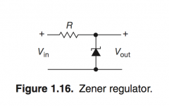
The circuit is very simple (attached). Here are my measurements @ R = 600 Ohm:
Vin = 22, 23, 24, 25 V
Vout = 18.01, 18.16, 18.32, 18.47 V
Iz = 6.7, 8.1, 9.46, 10.85 mA
Calculations:
dVin = 3V
dVout = 0.46V
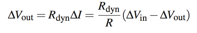
Rz = R x dVout / (dVin - dVout)
Rz = 600 x 0.46 / (3 - 0.46) = 276 / 2.54 = 108.6 Ohm
The specs says Rz is 21 Ohm at 7mA
Now, before you say the reason for the discrepancy is that my Iz is over 7mA, here is Rz value as measured for 22-23V change (where the current is very close to 7mA):
Rz = 600 x 0.15 / (1 - 0.15) = 90 / 0.85 = 105.9 Ohm
What am I doing wrong?
Mouser Part #: 512-1N5248BTR
Manufacturer Part #: 1N5248BTR
http://www.mouser.com/ds/2/308/1N5248B-1118236.pdf
While measuring Rz of 1N5248B zener I am getting the value much greater than the specs.
The circuit is very simple (attached). Here are my measurements @ R = 600 Ohm:
Vin = 22, 23, 24, 25 V
Vout = 18.01, 18.16, 18.32, 18.47 V
Iz = 6.7, 8.1, 9.46, 10.85 mA
Calculations:
dVin = 3V
dVout = 0.46V
Rz = R x dVout / (dVin - dVout)
Rz = 600 x 0.46 / (3 - 0.46) = 276 / 2.54 = 108.6 Ohm
The specs says Rz is 21 Ohm at 7mA
Now, before you say the reason for the discrepancy is that my Iz is over 7mA, here is Rz value as measured for 22-23V change (where the current is very close to 7mA):
Rz = 600 x 0.15 / (1 - 0.15) = 90 / 0.85 = 105.9 Ohm
What am I doing wrong?
Mouser Part #: 512-1N5248BTR
Manufacturer Part #: 1N5248BTR
http://www.mouser.com/ds/2/308/1N5248B-1118236.pdf
Attachments
Last edited:
Seems to me you've done nothing wrong.
Rdynamic is the slope of the I-vs-V curve: Rdynamic = dV/dI
Plugging in your values, Rdynamic = (18.47 - 18.01) / (0.01085 - 0.0067) = 110.8 ohms
Nowhere near 21 ohms. Maybe you accidentally purchased counterfeit parts from a sketchy seller on a super low priced foreign website.
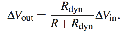
Dynamic resistance is terribly important in voltage reference designs, since the "line regulation" at DC is simply a voltage divider between Rbias and Rdynamic. The lower the dynamic resistance of the zener, the greater the line regulation -- i.e., the lesser the impact of changing input voltage.
Rdynamic is the slope of the I-vs-V curve: Rdynamic = dV/dI
Plugging in your values, Rdynamic = (18.47 - 18.01) / (0.01085 - 0.0067) = 110.8 ohms
Nowhere near 21 ohms. Maybe you accidentally purchased counterfeit parts from a sketchy seller on a super low priced foreign website.
Dynamic resistance is terribly important in voltage reference designs, since the "line regulation" at DC is simply a voltage divider between Rbias and Rdynamic. The lower the dynamic resistance of the zener, the greater the line regulation -- i.e., the lesser the impact of changing input voltage.
Last edited:
They are Fairchild parts purchased at Mouser.
This might shed some light on the issue:
https://www.vishay.com/docs/84117/84117.pdf
I had understood that these measurements need to be performed on a dynamic basis to avoid heating the junction which results in some errors.
This might shed some light on the issue:
https://www.vishay.com/docs/84117/84117.pdf
I had understood that these measurements need to be performed on a dynamic basis to avoid heating the junction which results in some errors.
I did notice the current go down and voltage go up in my measurements and I always recorded the value after the diode thermally stabilizes. Here is a new set of measurements, this time I recorded the very first value I could see on my DMM after connecting the zener:
Vin = 20, 21, 22, 23V
Vout = 17.38, 17.44, 17.48, 17.56V
Iz = 4.42, 5.96 7.56, 9.09mA
Plugging in these numbers I get a value much closer to the specs:
Rz = 600 x 0.16 / (3 - 0.18) = 108 / 2.82 = 38.29 Ohm
I am still surprised that I cannot rely on the Rz in the specs for such a simple application as voltage regulator. The text book I am reading also mentions that "the dynamic resistance of a zener diode varies roughly in inverse proportion to current". Statement that makes little practical use given how much junction heat from higher current can influence Rz in the opposite direction.
Last edited:
<snip>
I am still surprised that I cannot rely on the Rz in the specs for such a simple application as voltage regulator.
I think you have got it backwards, you can trust the manufacturer specification and not the measurements you are doing, the problem you have is that you cannot verify the specification because you don't have the appropriate equipment nor experience to make this measurement. No reason to feel bad, I don't either and would undoubtedly get similar results to yours.
As I pointed out this is a dynamic measurement and needs to be done on the order of milliseconds in order to avoid heating the junction. Even in the second or so it took you to do the measurement I suspect an error of > 100% based on the way the parts are generally specified.
Fairchild was a very reputable semiconductor maker, and their successor OnSemi is as well. Mistakes happen but it's not that likely over this period of time on a commodity part that such an error would not have been corrected. Unlike the old days most semiconductor devices today are 100% tested during production. (By convention some parameters guaranteed by design are not tested)
I have worked for several ATE semiconductor test hardware companies and designed hardware to do these sorts of measurements, it is not as trivial as it seems.
I think a good measurement method would be to feed the zener with say 10mA DC with 1mA ac superimposed, through a series R.
Measuring the attenuation of the AC signal before and after the series R should give you Rdyn.
Jan
Measuring the attenuation of the AC signal before and after the series R should give you Rdyn.
Jan
I don't feel bad. I am surprised that I take a (fairly basic) textbook example and am not able to reproduce it with an off the shelf zener, and the margin of error is magnitude of 5.
Granted, Horowitz and Hill in "Art of Electronics" use a different zener diode, 1N4733, however my hunch tells me I would run into similar problems.
Well, I learned something today, so this is good.
1. Zener diodes are very sensitive to heat (even at normal operating conditions) and make horrible DC voltage regulators (at least judging by this zener)
2. Don't take datasheet numbers for granted, there can always be caveats, sometimes you have to look for them elsewhere
I just measured some samples from my 18V drawer.
Measurement is made @7mA, and "properly", but I didn't care to make it extra-accurate (let's say, +/-10%):
BZX85 Motorola: 7.5Ω
Motorola-sourced HP part 1902-0679, cherry-picked ZD18 or similar: 3Ω (but incredibly noisy, making the measurement difficult)
BZX55 Philips: 5Ω
Oriental commodity crap, bought <1c apiece, no mark except voltage: 16Ω
BZX79 Philips: 6.5Ω
BZV58 ST: 4Ω, extremely noisy too
The conclusion: crap remains crap, but there are tradeoffs too: very low Rd means high noise.
The best tradeoff of my samples seems to be the BZX55 (dates back from the eighties or nineties - if you buy it now, your mileage may vary)
So? It's also true many things in electronics are. Most zeners basic parameters are given at fixed Iz. It may be a wise thing to consider current sources when using zeners. A fixed resistor only approximates one at higher values.1. Zener diodes are very sensitive to heat (even at normal operating conditions) and make horrible DC voltage regulators (at least judging by this zener)
Each zener voltage has a temp coeff. associated with it >> look close at the data sheet for the whole series of zener, not the individual part no. You can learn much more. Look at the list of parts in a column format. You'll notice @ some certain range of Zvoltage the T coefficient changes direction. So by selecting parts and tweaking the current source the coefficients might be balanced almost perfectly. ..You can build your own crude Tcomp zener from regular 6.x V parts. Heat guns and cool spray are basic tools in labs.
2. Don't take datasheet numbers for granted, there can always be caveats, sometimes you have to look for them elsewhere
Knowing how to look at data sheets is a learned skill, based on having a good foundation of solid state theory plus math. The caveats are there , look close at the test diagrams and notes. Some data sheets are better than others.. RIP National Semi Linear data book. Don't forget the almighty TL431 instead of simple zeners, they make simple yet excellent shunt regulators.
Last edited:
This thread is a wonderful example of how making a measurement (in this case of dynamic resistance) requires the correct application of theory to raw data (the numbers on the meter). By omitting the effect of heat, a number was obtained which was a factor of 5 wrong.
I didn't measure it, I simply noticed it was superimposed on the low amplitude sinewave resulting from the measurement, but measuring it would have been as easy: you just have to remove the AC stimulus current, and measure the amplitude of the noise using an AC milli- or microvoltmeter, generally in a definite bandwidthHow do you measure zener noise?
The affect of Tj could be minimised by clamping the leads as they exit the body. If you had a square wave generator, you could set it up to pulse the zener, and use an oscilloscope for measurement - the loss of metering accuracy shouldn't be too significant. But that is just remeasuring what the manufacturer has done.
Perhaps the art of datasheet interpretation is to note how your application is different from the manufacturer's test conditions, and to then look around for additional info to appreciate what is likely to be experienced in your application.
Perhaps the art of datasheet interpretation is to note how your application is different from the manufacturer's test conditions, and to then look around for additional info to appreciate what is likely to be experienced in your application.
- Status
- Not open for further replies.
- Home
- Design & Build
- Parts
- Zener dynamic resistance discrepancy