Hi dear solid state amp enthusiasts,
I was looking at Zeck PT9 PA circuit diagram but I couldn't figure out its input stage. I see the opamp (NE5534) in NFB loop but I have no idea about how does it couples/drives the other stages of the amplifier since the output severely loaded with a 100R resistor. Can anyone comment on this topology?
Thanks in advance.
Attachments
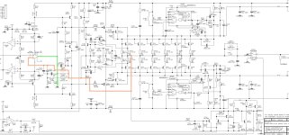
The output of Op-amp is heavily loaded, causing according ic supply current ripple.
This supply current ripple feeds the amp.
This supply current ripple feeds the amp.
Thanks @bucks bunny mystery solved.
Interesting... thus, amplifier is DC coupled, I guess. I didn't see such an implementation before. I would like to listen one of these amps.
Interesting... thus, amplifier is DC coupled, I guess. I didn't see such an implementation before. I would like to listen one of these amps.
I have seen this sometimes in the past.
Just one way to adapt low-supply voltage op-amps to hi-supply voltage power stage.
Never liked it that much, because of the uncertainty of op-amp quiescent current consumption
and possible other imperfections not found in the data sheets.
Just one way to adapt low-supply voltage op-amps to hi-supply voltage power stage.
Never liked it that much, because of the uncertainty of op-amp quiescent current consumption
and possible other imperfections not found in the data sheets.
This is a very interesting design. I'm an admirer.
I think of the opamp's output stage as the inverting input of a current feedback amplifier. That is, the emitters of its output transistors are inputs and receive current feedback from PA output (i.e. established by R248,249,250/R251,252). The collectors of the opamp transistors drive common base transistors T204 and T205. In effect, they are the upper stages of cascode pairs driven by the opamp's output transistor collectors.
At DC, the opamp's inverting input sees the PA output via R250, so it has unity gain at DC.
At audio frequencies, feedback forces the input signal to appear "virtually" at the opamp inverting input, and thus at the junction of R259 and R259. I compute the attenuation of the R248,249,250,251,252 network at the junction of R259 and R259 to be PA output x 0.01838. Gain is the reciprocal or 55.4, equal 34.7dB.
