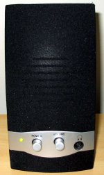
The small stereo PC amplifiers uses small speakers, and this turn them unable to reproduce deep bass.
Also they use a very simple power supply, a full wave rectifier and 1000uf filter... this is not enougth.
They can produce half watt each channel, and you will be surprise how good and loud this power can be if you produce modifications and use bigger and better speaker system.
Those chips uses electrolitic condensers into the output, again to reduce manufacturing costs, the value there is 220uf or 470uf, when 2200uf can be much better allowing you to listen deep bass tones... the output condenser, after increased, must be bypassed with a capacitor...100n to 2.2uf will be good to bypass.
The input need filtering to ground.... i have used 100N, you can try other values.
A very good idea is to increase the zobel filter capacitor, install there more 220N to each channel naturally.
But the better modification is to assemble an LM7808, or LM7806 voltage regulator inside the case... using 2200uf into the input and 2200 into integrated circuit output.
The chip you have inside is not a bad one.... sounds good and the distortion is 0.4 percent into the maximum power and you can use it to 0.1 percent reducing a little your volume...just do not use full throotle power.
It can be used as a pré amplifier as it is able to ouput clean (reasonable cleanO 1.5 volts RMS to each channel (0.55 W)
An Orkut friend have asked me and i have produced Youtube small video to show him how nice can be the sound.
Observe that Digital cameras are not able to record deep bass...and the bass reproduced were very low in frequency and the audio quality was very good... video will not show how good it was, but can provide you some idea.
http://www.youtube.com/watch?v=d1PCkmZWTPs
regards,
Carlos
Attachments
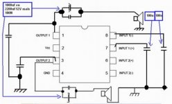
Schematic to help you.
attached
regards,
Carlos
..................................................................................................
To the output condenser, to use in parallel with them, 2.2 will be effective... 100N will not help... please, correct that.
attached
regards,
Carlos
..................................................................................................
To the output condenser, to use in parallel with them, 2.2 will be effective... 100N will not help... please, correct that.
Attachments
To identify the output observe the speaker wires and also
2 electrolitic condensers that you may found very close one each other.
To identify the input, use the "finger super signal injector"... touch the input pins and you will be able to find them.
Of course, you can download the chip datasheet into the WEB.
regards,
Carlos
2 electrolitic condensers that you may found very close one each other.
To identify the input, use the "finger super signal injector"... touch the input pins and you will be able to find them.
Of course, you can download the chip datasheet into the WEB.
regards,
Carlos
Attachments
Another helping image.
You will appreciate the result, also using headphone you will perceive no more mains noise together your audio.
As you see, the way i use to do, all ideas offered were tested, assembled real life...nothing that was made into simulator, nothing was untested... result is guaranteed.
regards,
Carlos
You will appreciate the result, also using headphone you will perceive no more mains noise together your audio.
As you see, the way i use to do, all ideas offered were tested, assembled real life...nothing that was made into simulator, nothing was untested... result is guaranteed.
regards,
Carlos
Attachments
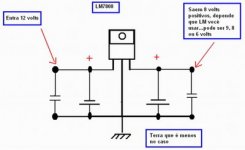
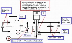
If you have not any step down voltage regulator alike LM7806
or LM7808, or LM7809... then you can produce your own using any NPN transistor you may have into your junk box.... power is small, so, maybe you will not even need heatsink.
Select zener diode depending your chip amplifier voltage.... they use to operate using 6 volts and can tolerate till 15 volts...so.. select zeners to allow you to obtain voltages from 6 to 9 volts to be more safe to the small chip.
Voltage will appear into the output added by 0.6V that is the base to emitter voltage...so... a 5V1 zener will result into 5V7 volts into the output.
Use the condensers you have.... nothing is critical into this small voltage stabilizer, a step down regulator, helpfull and easy... i have assembled "zilions" into this life...so...guaranteed.
LM7908 and others that has the number "9" instead of "8"... are negative regulators...made to adjust negative voltages...to use those ones you will have to invert zener, electrolitic condensers and your input polarity....output polarity will be inverted too if you watch the schematic i have provide you.
regards,
Carlos
Attachments
Did this on daughters PC speakers....
317 cost $0.22 ,is better than 78XX's (less ripple, more amps)
Circuit above is short proof (D2) no .
.
Most cheap pc speakers I see use 9-12v with AN7124 or
similar 3-5w chipamp.
these can take Vcc 24v ,so give em' 18 V +
better ones (small logitech or ESS) will use a cheap PS( 12-15V
wall unit) with a better IC (LM XXX-10watt+) Use a fully
heatsinked 317 with a VCR transformer(20VAC), run at 20-24V
and you will be loud..
ALWAYS look to amp board to replace any 16V caps with 25-35v
ones . Also one might want to put a larger heatsink on the
amp IC as well..
PS ,you can also make the 78XX's adjustable /higher voltage
by floating the ground (circuit above) and give protections
(D1-2).🙂
An externally hosted image should be here but it was not working when we last tested it.
317 cost $0.22 ,is better than 78XX's (less ripple, more amps)
Circuit above is short proof (D2) no
.Most cheap pc speakers I see use 9-12v with AN7124 or
similar 3-5w chipamp.
these can take Vcc 24v ,so give em' 18 V +
better ones (small logitech or ESS) will use a cheap PS( 12-15V
wall unit) with a better IC (LM XXX-10watt+) Use a fully
heatsinked 317 with a VCR transformer(20VAC), run at 20-24V
and you will be loud..
ALWAYS look to amp board to replace any 16V caps with 25-35v
ones . Also one might want to put a larger heatsink on the
amp IC as well..
PS ,you can also make the 78XX's adjustable /higher voltage
by floating the ground (circuit above) and give protections
(D1-2).🙂
the best thing
to obtain perfect sound from a pc card and pc generally
the first and only thing you need to do is to remove the output chip from the sound card ....thus gain from your pc the true line out .....
most of the characteristics of the output chip is based on the ability to drive directly headphones or small speakers meaning that inside the card the output chip something like 4558 smd can produce a few milliwatt but has terrible bandwidth..... and terrible crosstalk .....and terrible stereo image .....
On the other hand the pc it shelf just right after the D/A has all these wonderfull features all included ....
the only problem is that this specific line out no matter how clean and nice is kinda low ....
this way you will listen very nice music from your pc ....
done and tested in all my pc's so far
for andrew and others
andrew there is no secret to it ....
1- you cannot do this to on board sound cards of course
2-in any other sound blaster or so just behind the so called line out of the card you will see a 4558 smd or simular op amp
3- you check the pin out of the chip and find the input
4-A) you may keep the chip as is and add two caps like 0.47-1mfd in the input of the chip and get the "line in " of the chip for your own use and then add acouple of isolated phono plugs on the pc
4-B) gut off the chip totally remove all related componeds and bypass input and output of the chip with 2 caps 0.47-1mfd and this will give you the line out of the pc DAC directly to your 3.5 mm mini jack
i dislike mini jacks very much so in my pc's i always use phono plugs
except my office pc all the rest of the pc i have is mostly for rental applications used with VESTAX+TRACTOR as dj sets and some others also as video consoles so sound is very critical from devices like that .....
still, mod like that will provide a quiet low output but then most of my systems will work togeteher with 16/24/32 ch mixers so gain is provided by the mixer
to my office i was lucky enough to have speakers that gain was no problem
some of us older
might remember that sound cards in the past had a pair of jumpers to define output to either "speakers" or "line out "....
now days we have to many on board sound cards and also this so called line out chip that is supposed to provide actually both ....so signal of the chip is actually something in between ....
some of us are allready equiped with external sound cards that do provide a real line out
the above way is a very simple and cheap way to produce perfect sound from a simple sound blaster and so on
Ups!.... sorry.... wrong product... this is for bugs
those insect goes flying and buzzing around us.... bugger things.
Ostry is not the one...he is a lovely friend.
I have changed the perfum can for an insect killer.
heheheheh..... Bzzzzzz!.... BOOOM!
Be happy folks!
Life is the one and only we have...no one returned from death to guarantee we will have more lives...so..enjoy the one you have.
regards,
Carlos
- Status
- Not open for further replies.
- Home
- Amplifiers
- Solid State
- You PC amplifier can be modified to produce better sound