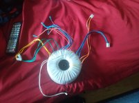
This one is a bit more complicated than most, as it appears to have multiple sets of windings.
A google search of the model number (td-230-0500) brings me to here: Toroidal Transformers
However, it doesn't tell me much, and it also states that the transformer is for 230V input, but it came out of a 110/120V device.
I'm just trying to identify what wires are for what, and a good way to test them, given that I don't have much in terms of higher-voltage test equipment. If it ends up a suitable choice, I would probably end up using this for some higher powered amplifier power supply somewhere down the road.
Thoughts?
Attachments
Try...
Question/then:
Looks like the blue and red wires with the spade lugs are the primary.
Do u have a vow meter? Then...
Take a low voltage wall wart and an ext cord u can cut and strip. I would connect them to the blue and red. Then read out the other wires out for the voltage value. It will will be a ratio, 30vac in and 10vac out is a ratio of 3:1, 120vac in : 40v out.
Or google for a good link
That makes sense. I've got all sorts of testing gear, just most of it more suitable for <100V applications, although they'll do higher. Looking around, I found an adjustable 9-13VAC wall wart I can cannibalize.
There's two blue, two brown, and one red that go into the middle with the spade terminals. Two primaries, with a ground? I have no idea, but an odd number of wires makes me wonder. The rest I can find with my meter.
Thanks,
There's two blue, two brown, and one red that go into the middle with the spade terminals. Two primaries, with a ground? I have no idea, but an odd number of wires makes me wonder. The rest I can find with my meter.
Thanks,
BL-BL and BR-BR are 0 ohms, BL-BR are both ~1.2 ohms, can't find anywhere that the red matches up with.
Ignore that last statement, the three on the right (BL-BR-RD) all measure with each other. Reads about 1 ohm with the blue, below probe contact (0.1) ohm with the brown
The wall wart just makes a safer voltage.
Usually, most of the time, if the two BRN have a physical connection and the red does also, but not the red and BRN. The connection would be red/BRN. Red/BRN connected together for 120v supply to each, and for 220v, one red connected to one BRN, and the loose, unconnected, red wire to one supply line and the loose unconnected, red wire to the other supply line.
I gutted an adcom 5552 except the tranny and supple caps, wired it for 220v and hooked it up to the USA 120v so I could cut the secondary voltage in half.
I am getting upset with the tech and his trouble shooting procedures. Pretty soon she will tell the wife that earths gravity has shifted in our house.
So it's the blue and BRN are the pairs.
Yeah, blue and brown pairs are identical to each other, but only ONE of the two pairs has a connection with the red as described.
I am getting upset with the tech and his trouble shooting procedures. Pretty soon she will tell the wife that earths gravity has shifted in our house.
lol that'll happen. make up some shyt about hacking him if he keeps it up
anyway, should I be worried about any excess current draw on that wall wart since the primaries appear to have a DC resistance of about 1 ohm?
If the transformer is not loaded up on the secondary, there should't be a problem. If it doesn't have a volt/ampere rating, find out what the max wattage the device draws the transformer was removed from. Power(watts) will be the same on both sides plus transformer efficiency, which is very small. Use a wall wart with at least 1/2 amp.
with 12VAC applied to blue-brown pair
OR - BK - OR
2.6 0 2.6
BL - BK - BL
3.2 0 3.2
GN - BK - GN
1.85 0 1.85
YLW - YLW
1.2
OR - BK - OR
2.6 0 2.6
BL - BK - BL
3.2 0 3.2
GN - BK - GN
1.85 0 1.85
YLW - YLW
1.2
At12vac in, 2.6 out, and 3.2out would be equal to 120vac in , 26 vac out and 32vac out.
Larger wire can indicate higher current carrying conductors, or with higher voltage more insulating, safer. It takes some guess work without knowing what they were connected to.
Larger wire can indicate higher current carrying conductors, or with higher voltage more insulating, safer. It takes some guess work without knowing what they were connected to.
- Status
- Not open for further replies.
- Home
- Amplifiers
- Power Supplies
- Yet Another Transformer Identification Thread