Hi!
I'm a complete beginner at building audio circuits, but I thought it would be fun to design and build a Class D-amplifier. I know, maybe it shouldn't be your first project, but I like a challenge.
Anyway, I went for a self-oscillating design, loosely inspired by a bunch of different designs out there. Pretty simple stuff. I take a ground references signal from an RCA plug, split it up into an inverted and a non-inverted signal, run it through an integrator that's fed back by both sides of an H-bridge, then through a regular comparator and MOSFET driver.
To my great surprise, the thing actually produced sound when I hooked it up to a speaker. However, it has three issues:
1) It takes a couple of seconds, sometimes longer, for it to reach stable oscillation. During that time, it produces awful scratchy noises.
2) The oscillation seems unstable. RV2 can be used to tune the idle oscillation frequency and I have to tune it to a very specific point (happens to be 192kHz) for it to produce a stable signal. Just a 1/16 of a turn on the pot, and it starts hissing and scratching.
3) The output from the MOSFETS has a lot of positive overshoot. Not sure if this affects anything.
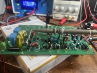
Attaching the schematic. And no, I don't expect you to fix my issues, but a pointer in the right direction might be nice!

I'm a complete beginner at building audio circuits, but I thought it would be fun to design and build a Class D-amplifier. I know, maybe it shouldn't be your first project, but I like a challenge.
Anyway, I went for a self-oscillating design, loosely inspired by a bunch of different designs out there. Pretty simple stuff. I take a ground references signal from an RCA plug, split it up into an inverted and a non-inverted signal, run it through an integrator that's fed back by both sides of an H-bridge, then through a regular comparator and MOSFET driver.
To my great surprise, the thing actually produced sound when I hooked it up to a speaker. However, it has three issues:
1) It takes a couple of seconds, sometimes longer, for it to reach stable oscillation. During that time, it produces awful scratchy noises.
2) The oscillation seems unstable. RV2 can be used to tune the idle oscillation frequency and I have to tune it to a very specific point (happens to be 192kHz) for it to produce a stable signal. Just a 1/16 of a turn on the pot, and it starts hissing and scratching.
3) The output from the MOSFETS has a lot of positive overshoot. Not sure if this affects anything.
Attaching the schematic. And no, I don't expect you to fix my issues, but a pointer in the right direction might be nice!
Hmmm... VB on the IR2184 should be hooked to DRIVE+ and not 12V, right? Isn't that what's biasing the gate voltage?
Last edited:
Uhm. No. Oops. blush I’ll whack in a 10uF and a 100nF ceramic. And you mean that 12V is ground reference and therefore shouldn’t be used for VB, right?
You think these issues could also be what’s causing the stability problems?
You think these issues could also be what’s causing the stability problems?
Think the 12V seems ok.
Stability problem is possibly related to the loop feedback. Circuits like this have a pair of HF poles in the RHP
that require strong compensation. Try reducing the BW with a dominant pole around 10x lower than what you have now.
Stability problem is possibly related to the loop feedback. Circuits like this have a pair of HF poles in the RHP
that require strong compensation. Try reducing the BW with a dominant pole around 10x lower than what you have now.
Thank you! A 10uF cap between top and bottom of each half bridge took care of the overshoot. I feel kind of silly to have missed that! As for introducing new poles, I’m trying to wrap my head around how to analyze something as non-linear as this and even get a decent AC analysis in SPICE. I’m assuming there’s a lot of trial and error. Are there any “tried and tested” points of attack I could try before I dive too deep into the AC analysis abyss? (My math is a bit rusty, to say the least)

Try increasing the C10/C11 feedback capacitors.
If this helps, increase them some more.
What is RV2 for?
If this helps, increase them some more.
What is RV2 for?
Last edited:
Those caps aren’t for feedback. They form an integrator together with the opamp and RV2. RV2 is for setting the idle resonance frequency of the loop.
The integrator bandwidth, set by the feedback capacitors, may be excessive, causing the instability.
Last edited:
Ok. Time to show my ignorance, but how do I lower the bandwidth of an integrator without reducing the idle resonance frequency of the entire loop? It’s at 200kHz now and that’s a little less than I’d like.
If it wasn’t clear from my initial post, this is a self oscillating design. At idle it’s supposed to oscillate at 200-300kHz. So I’m not sure how I can lower the bandwidth without messing up the self oscillation.
What I mean by “not stable” was that the oscillation kept jumping around in phase and frequency creating a scratchy noise. A lot of it went away when I added caps across the half bridges, but there’s still some hiss left. It may be due to grounding issues.
You want some small value capacitors across the audio inputs to attenuate high frequency noise,I built a H bridge ucd type some time ago and it sounded pretty good until one side of a fake ir2110 gave out and later when I shorted some leads.I'll get back to it when finish building some subs,Also the layout is pretty important

Thanks! Yeah, some lowpass filtering on the input is on my TODO list. Like a 40kHz cutoff of something like that.
As for the layout, did you go with a 4-layer PCB with solid ground planes, or just two layers? The 4-layer boards get pretty expensive to make.
As for the layout, did you go with a 4-layer PCB with solid ground planes, or just two layers? The 4-layer boards get pretty expensive to make.
Also, did you experience startup issues? Mine takes a second or two of unpleasant sounds to lock into the idle frequency. Is there a way to make it lock in quicker or should I just hide it with a soft start circuit?
I went with single layer,hiss was audible but I used 20 meters of telephone wire to hook it up to my computer,when I shorted the input the hiss was barely audible from half a meter away
And you didn't have any startup problems? Mine usually takes 1-2 seconds to reach stable oscillation. Before that there's a lot of unpleasant scratching. Every once in a while it takes a lot longer to get into stable oscillation.
On a positive note: Apart from the slight hiss (which I think is easily fixable), it sounds AMAZING! Crazy power with almost no power dissipation.
On a positive note: Apart from the slight hiss (which I think is easily fixable), it sounds AMAZING! Crazy power with almost no power dissipation.
With the ucd type no, it starts imediatelly when it receives power, but with a d4k5 i built and tweaked, similar technology to yours but half bridge, it would never power on unless given sufficient input signal,I would pop and crackle, eventually fart and then start,i'm not sure why but I think it has to do with the gate driver wanting to build bootstrap voltage but not being able to because the amplifier latches in positive output mode upon startup and bootstrap voltage cannot be built without turning on the lower mosfet,but this issue may be automatically fixed with a full bridge since there is a path to ground,and 4001 is way too slow for the bootstrap you need a high speed diode like the ones from switch mode power supplies,this could also cause problems
- Home
- Amplifiers
- Class D
- Yet another noob