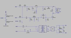
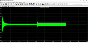
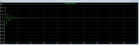
Here is yet another inrush current limiter. The circuit is straightforward, and component values need not be precise. Also attached are two plots: one showing the line current with the limiter and the second without the limiter. Needless to say, the large current/voltage transients encountered without limiting are not good for the life of the filter caps or other components.
I have implemented this circuit and variants thereof for both inrush limit and output connect, where the latter was used to prevent turn-on transients from appearing at the amp/preamp output. The circuit also implements asymmetric turn-on and turn-off characteristics, such that a transient line power loss results in a reset and full delay time to relay close.
I have implemented this circuit and variants thereof for both inrush limit and output connect, where the latter was used to prevent turn-on transients from appearing at the amp/preamp output. The circuit also implements asymmetric turn-on and turn-off characteristics, such that a transient line power loss results in a reset and full delay time to relay close.
Attachments
Why not measure (rather than simulate) the current at switch-on, using an audio amplifier with big power transformer and lots of filter capacitance?
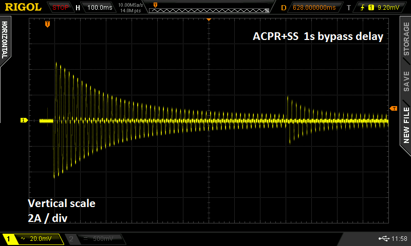
Once the circuit is built I will make some measurements with a clamp-on ammeter that has outputs to a scope. That said, I have a fairly high degree of trust in the simulations.