Hi,
here I'm documenting my my current line array build. I'm mostly done with the wood working and have set up a basic DSP. A Raspberry Pi Zero running Funtoo Linux (a Gentoo derivative) + BruteFIR. Why not Raspbian? In my experience Gentoo based distros run faster than Debian ones (obviously useful on slow devices) since your system is tailored exactly to the hardware. But that discussion is fuel for endless flame wars, so I stop here. 😀
Back to the topic. The Pi is connected to a CM6206 based USB interface (8 analog 16 bit / 48 kHz outputs, two inputs. Plus Toslink in and out). Filter coefficients are created via DRC Designer on my measurement laptop running Windows 10 (I'm planning to do the filter creation directly via DRC-FIR on the RPi to simplify things and get rid of Windows).
Just a few hours ago I've finished the BruteFIR configuration. I'm getting music out and the CPU load is on a moderate level (~63%), no clicks and pops but it sounds awful, like a 64 kBit MP3 or worse, no highs. I'm getting better sound by only using the built-in 10 band EQ from my media player. I'm awaiting another USB sound card to be delivered in a few days so I can measure what's being wrong exactly.
I think I'm going to correct the low frequency roll off via a Linkwitz transform circuit straight down to 20 Hz (Yes, that's a ton of gain, fc is around 140 Hz. Small sealed enclosures need a lot of power, total enclosure volume per driver is 0.75 l...) and do the 3 dB/oct high frequency fall off compensation via analog circuity too and leave the fine adjustments to DRC-FIR.
Here's my current BruteFIR config, if someone is interested, two channels, one way. I had to convert the stereo .wav from DRC Designer to two mono raw files via the tool sox to be accepted by BruteFIR.
I've started the build on Oct 26. Here are some pictures:
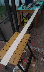
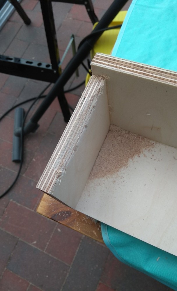
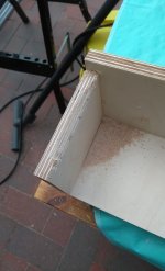
1 - First baffle chamfered on the back side
2 - Preparing the second baffle
3 - Both baffles done
4 - Cut outs on the first baffle done
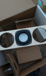
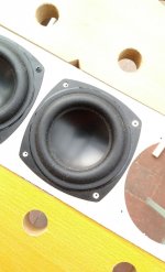
5 - Driver fits 😀
6 - Cutting out the second baffle
7 - Both baffles done
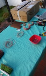
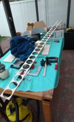
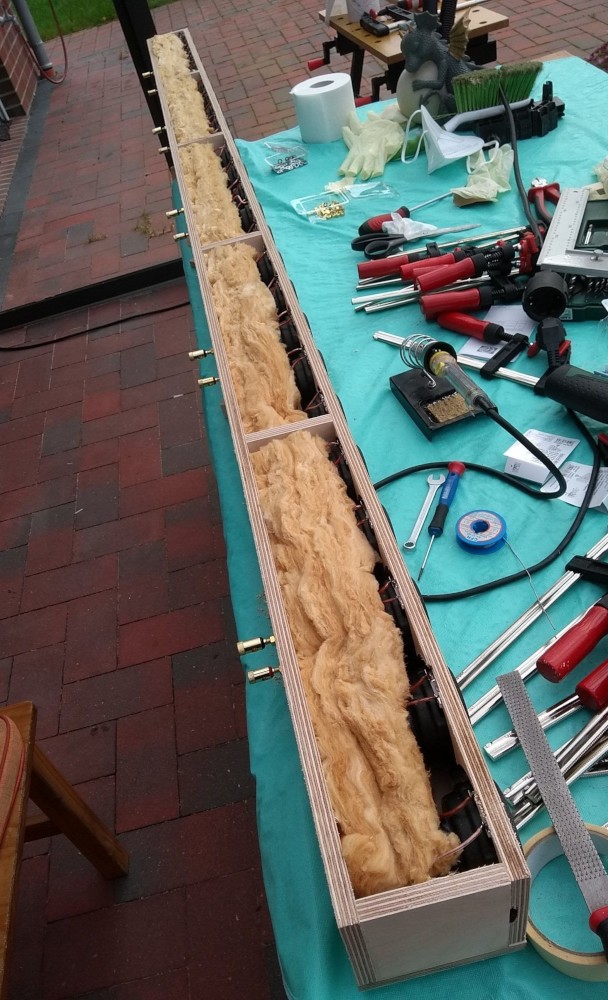
8 - Preparing internal cabling. Five drivers in series, five groups parallel for 8 ohms impedance or all in series (200 ohms) for OTL experiments (I have lots of 6P45S sweep tubes to be used and enough power transformers for circlotron amps)
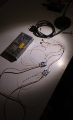
9 - Hooked up some cheap chinese 30W Class D chip amps for testing purposes
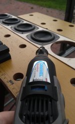
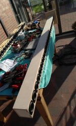
10 - Drilling 200 holes... 😕
More pictures in the following posts.
here I'm documenting my my current line array build. I'm mostly done with the wood working and have set up a basic DSP. A Raspberry Pi Zero running Funtoo Linux (a Gentoo derivative) + BruteFIR. Why not Raspbian? In my experience Gentoo based distros run faster than Debian ones (obviously useful on slow devices) since your system is tailored exactly to the hardware. But that discussion is fuel for endless flame wars, so I stop here. 😀
Back to the topic. The Pi is connected to a CM6206 based USB interface (8 analog 16 bit / 48 kHz outputs, two inputs. Plus Toslink in and out). Filter coefficients are created via DRC Designer on my measurement laptop running Windows 10 (I'm planning to do the filter creation directly via DRC-FIR on the RPi to simplify things and get rid of Windows).
Just a few hours ago I've finished the BruteFIR configuration. I'm getting music out and the CPU load is on a moderate level (~63%), no clicks and pops but it sounds awful, like a 64 kBit MP3 or worse, no highs. I'm getting better sound by only using the built-in 10 band EQ from my media player. I'm awaiting another USB sound card to be delivered in a few days so I can measure what's being wrong exactly.
I think I'm going to correct the low frequency roll off via a Linkwitz transform circuit straight down to 20 Hz (Yes, that's a ton of gain, fc is around 140 Hz. Small sealed enclosures need a lot of power, total enclosure volume per driver is 0.75 l...) and do the 3 dB/oct high frequency fall off compensation via analog circuity too and leave the fine adjustments to DRC-FIR.
Here's my current BruteFIR config, if someone is interested, two channels, one way. I had to convert the stereo .wav from DRC Designer to two mono raw files via the tool sox to be accepted by BruteFIR.
Code:
## GENERAL SETTINGS ##
filter_length: 65536;

## COEFFS ##

coeff "left" {
	filename: "left.raw";
	format: "S16_LE";     # file format
};

coeff "right" {
        filename: "right.raw";
        format: "S16_LE";     # file format
};

## INPUT ##

input "left", "right" {
	device: "alsa" { device: "hw:0";};  # module and parameters to get audio
	sample: "S16_LE";   # sample format
	channels: 2/0,1;    # number of open channels / which to use
	delay: 0,0;         # delay in samples for each channel
	maxdelay: -1;       # max delay for variable delays
	subdelay: 0,0;      # subsample delay in 1/100th sample for each channel
	mute: false,false;  # mute active on startup for each channel
};

## OUTPUT ##

output "left", "right" {
	device: "alsa" { device: "hw:0";};  # module and parameters to put audio
	sample: "S16_LE";   # sample format
	channels: 2/0,1;    # number of open channels / which to use
	delay: 0,0;         # delay in samples for each channel
	maxdelay: -1;       # max delay for variable delays
	subdelay: 0,0;      # subsample delay in 1/100th sample for each channel
	mute: false,false;  # mute active on startup for each channel
	dither: false;      # apply dither
};

## FILTERS ##

filter "left" {
	from_inputs: "left"/0.5;
	to_outputs: "left"/0;
	coeff: "left";
};

filter "right" {
        from_inputs: "right"/0.5;
        to_outputs: "right"/0;
        coeff: "right";
};
I've started the build on Oct 26. Here are some pictures:
1 - First baffle chamfered on the back side
2 - Preparing the second baffle
3 - Both baffles done
4 - Cut outs on the first baffle done
5 - Driver fits 😀
6 - Cutting out the second baffle
7 - Both baffles done
8 - Preparing internal cabling. Five drivers in series, five groups parallel for 8 ohms impedance or all in series (200 ohms) for OTL experiments (I have lots of 6P45S sweep tubes to be used and enough power transformers for circlotron amps)
9 - Hooked up some cheap chinese 30W Class D chip amps for testing purposes
10 - Drilling 200 holes... 😕
More pictures in the following posts.
Attachments

I've got my second USB interface so I can do measurements of the filtered system now. I'll do that tomorrow (it's 10 pm here and I don't want to annoy the neighbors with sine sweeps...).
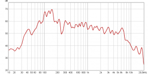
You want to see something ugly? 😀 I've got the in room response for you without any EQ!
Left:

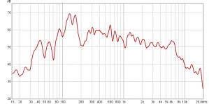
Right:

Lot's of EQ needed, but that's expected. The low end will be Linkwitz transformed. (drivers are able to dissipate 500 Wrms / 1000W peak, to reach the xmax of +-4.75mm I need that power) Sensitivity in the highs seem to drop to that of a single driver, well that's expected with point sources in an array at short wavelengths. But fortunately Le is pretty high. Z is about 55-60 ohm @ 20 kHz, so I only need lots of voltage swing, current is low (I have two IRS2092 boards rated at 300W / 8 ohm, 600W / 4 ohm, even capable to go down to 2 ohm) I consider getting another two and bridge them if I like the sound.
Also there are four 625 VA / 2x 50 VAC toroids waiting, so I should be able to get something like 1 kW continuous with 1.2 kW peaks out (continuous power limited by the transformers and I probably need to upgrade the heatsinks, they look like they can dissipate 10W or so, but I have an idea for that). Right now I only need to make a PSU board and a phase splitter for BTL operation.
More pictures...
Drivers fit:

Or not. I've done the calculations in my head and messed up the internal height, so I had to improvise:
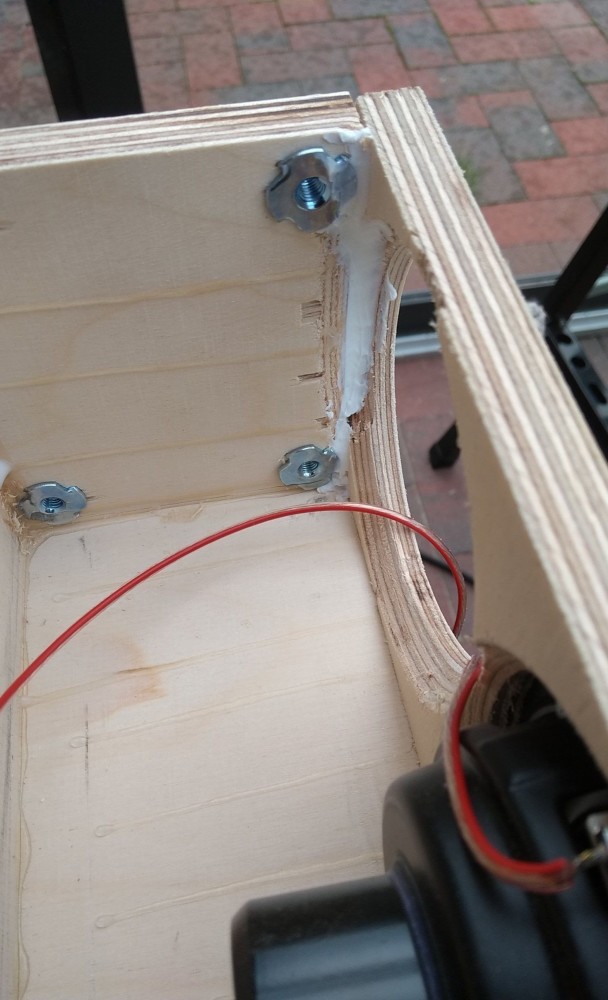
I'm using drive-in nuts for mounting the stand:
Stuffed the first cabinet (too much, raised fc to 160 Hz):
Put the side wall on to test how much the stuffing affects the impedance curve:
Measurment laptop + half stuffed enclosures (I've kept it that way):

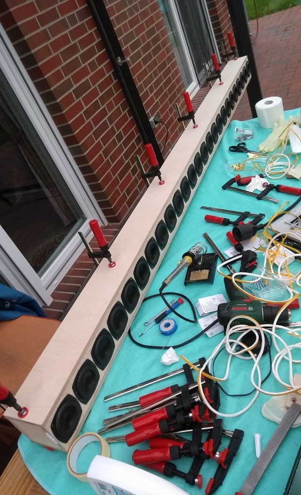
Gluing the first cabinet:
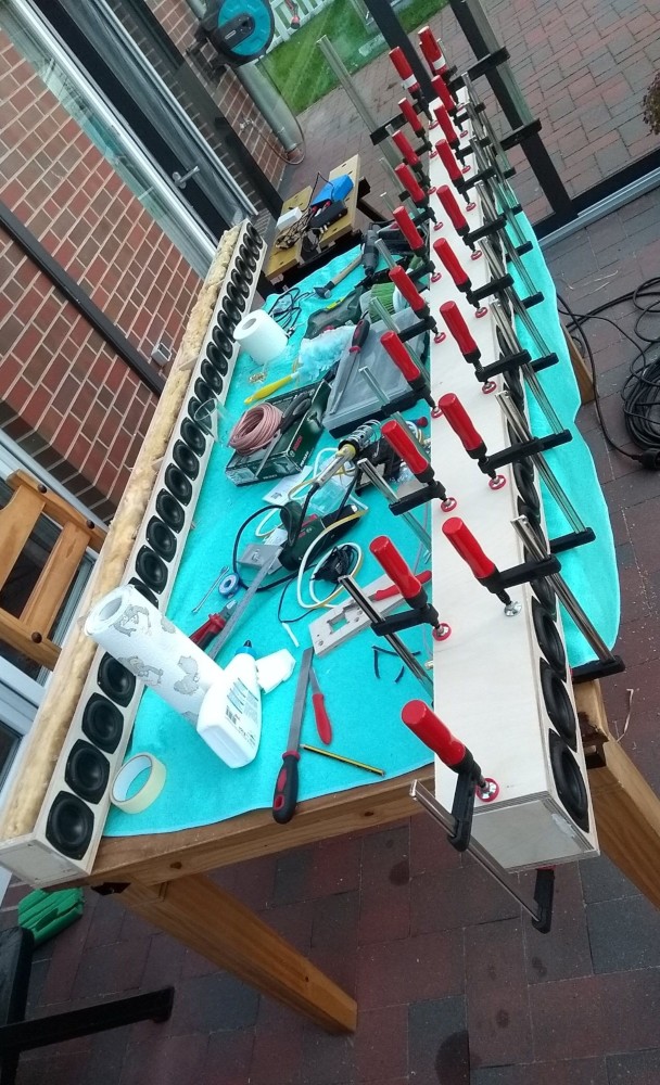
Finished gluing:
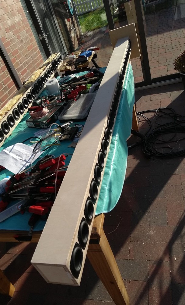
More pictures in the next post.
You want to see something ugly? 😀 I've got the in room response for you without any EQ!
Left:
Right:
Lot's of EQ needed, but that's expected. The low end will be Linkwitz transformed. (drivers are able to dissipate 500 Wrms / 1000W peak, to reach the xmax of +-4.75mm I need that power) Sensitivity in the highs seem to drop to that of a single driver, well that's expected with point sources in an array at short wavelengths. But fortunately Le is pretty high. Z is about 55-60 ohm @ 20 kHz, so I only need lots of voltage swing, current is low (I have two IRS2092 boards rated at 300W / 8 ohm, 600W / 4 ohm, even capable to go down to 2 ohm) I consider getting another two and bridge them if I like the sound.
Also there are four 625 VA / 2x 50 VAC toroids waiting, so I should be able to get something like 1 kW continuous with 1.2 kW peaks out (continuous power limited by the transformers and I probably need to upgrade the heatsinks, they look like they can dissipate 10W or so, but I have an idea for that). Right now I only need to make a PSU board and a phase splitter for BTL operation.
More pictures...
Drivers fit:
Or not. I've done the calculations in my head and messed up the internal height, so I had to improvise:
I'm using drive-in nuts for mounting the stand:
Stuffed the first cabinet (too much, raised fc to 160 Hz):
Put the side wall on to test how much the stuffing affects the impedance curve:
Measurment laptop + half stuffed enclosures (I've kept it that way):
Gluing the first cabinet:
Finished gluing:
More pictures in the next post.
Attachments


I like it too now, especially after tweaking the DRC-Designer parameters. 😀 (some are really sensitive, like the mid and high frequency correction strength which causes nasty ringing if overdone).
Here's the target response (note: I don't have a calibration file for my mic right now. So the curve likely changes once I have it calibrated):

I cut off everything below 40 Hz and somewhere above 15 kHz (the frequency scale in DRC-Designer isn't logarithmic and I can't really make sense of the values above 5 kHz, I need to measure the corrected system sometime...) to prevent excessive correction and subsequent amp clipping (sensitivity from a sealed enclosure with 18.75 liters is really low down there. I'm running 30W / 8 ohm amplifiers now, I'll order PSU parts for 300W / 8 ohm boards next week).
And the filter parameters:

As stated above, I easily hear nasty artifacts, especially out of the sweet spot if I overdo the mid-/high correction.
At my listening distance, I can't really make out comb filtering. Neither there are amp issues, these boards are really good especially for less than 2 EUR / piece (here: DC 8-26V TPA3110 PBTL Mono Digital Amplifier Board AMP Module 1*30W for Arduino | eBay), running on a 24 V / 150W Meanwell SMPS. I have eight amp boards in total, I might be getting more of these for subwoofer application (for lots of small drivers). I'm considering testing a crude DBA approximation with some cheap surplus drivers first (my listening room is asymmetrical, like a L so I'd need at least three channels with individual delays to cancel out the back wave).
Here are the remaining pictures from the build process:
First array assembled:

Second array getting glued:

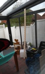
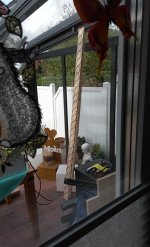
Preliminary placement in my room (excuse the clutter... 😀). I consider removing the stand, moving them completely into the corner and treating the first reflections with absorption panels, as much as it's possible. The old, disconnected floorstanders might have some use later. If I place a large AMT like the Dayton AMT Pro 4 on top of them, I get it exactly to ear level, since I have a currently unused pair of them to test it...

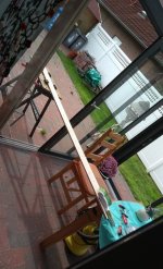
As much as floor-to-ceiling as it gets:

And placed into the corners as much as feasible:

Here's the target response (note: I don't have a calibration file for my mic right now. So the curve likely changes once I have it calibrated):
I cut off everything below 40 Hz and somewhere above 15 kHz (the frequency scale in DRC-Designer isn't logarithmic and I can't really make sense of the values above 5 kHz, I need to measure the corrected system sometime...) to prevent excessive correction and subsequent amp clipping (sensitivity from a sealed enclosure with 18.75 liters is really low down there. I'm running 30W / 8 ohm amplifiers now, I'll order PSU parts for 300W / 8 ohm boards next week).
And the filter parameters:
As stated above, I easily hear nasty artifacts, especially out of the sweet spot if I overdo the mid-/high correction.
At my listening distance, I can't really make out comb filtering. Neither there are amp issues, these boards are really good especially for less than 2 EUR / piece (here: DC 8-26V TPA3110 PBTL Mono Digital Amplifier Board AMP Module 1*30W for Arduino | eBay), running on a 24 V / 150W Meanwell SMPS. I have eight amp boards in total, I might be getting more of these for subwoofer application (for lots of small drivers). I'm considering testing a crude DBA approximation with some cheap surplus drivers first (my listening room is asymmetrical, like a L so I'd need at least three channels with individual delays to cancel out the back wave).
Here are the remaining pictures from the build process:
First array assembled:
Second array getting glued:
Preliminary placement in my room (excuse the clutter... 😀). I consider removing the stand, moving them completely into the corner and treating the first reflections with absorption panels, as much as it's possible. The old, disconnected floorstanders might have some use later. If I place a large AMT like the Dayton AMT Pro 4 on top of them, I get it exactly to ear level, since I have a currently unused pair of them to test it...
As much as floor-to-ceiling as it gets:
And placed into the corners as much as feasible: