Hi folks!
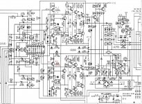
I have here a failing PM-53 with large DC offset at output. One of the chanels drives a couple of volts to the output. I have desoldered and ckecked all transistors past Q702/703, checked resistors, all OK.
Also, the other chanel sings OK, offset and bias are all OK.
Now, with desoldered components, measuring the voltages arround Q702 indicates, that the transistor is not operating. But, I can pull bassis down to ground with 10k resistor and get +38V on collector, instead of initial -41 Volts.
Does this looks like AN7062 is not driving Q702 properly? I can also manualy manipulate operation of Q702 by pulling (via 10k resistor) pins 4,5,6,7 to the ground! I have not tried to manipulate the other side, too risky to damage output trannies.
Floating voltage at pin 8 (desoldered) is arround +38V.
Thank you for answers!
Attachments
Totally obsolete now. Sorry.
You could make a driver/comparator for your amp, here is the pinout of the AN7062;
AN7062 Datasheet
You could make a driver/comparator for your amp, here is the pinout of the AN7062;
AN7062 Datasheet
I have original available if you are close enough
Do some checking if something is wrong with capacitors there
Do some checking if something is wrong with capacitors there
Hi there!
Done some additional tests. Capacitors were all ok except C705/706 C751/752 (30u instead 100u , and 3x higher ESR than new), but those were unlikely to couse drift.
All transistors (minus power Q761-764) were checked on curve tracer, all look OK.
Chanel was reasembled, but insted of power transistors, only diode was put in to mimic base-emitor junction. Because the DC servo is fed only from the last transistor pair, it is useles to make eny conclusions based on a open feedbak loop, as I did at the beginig.. In this configuration, AN7062 must be able to do a small amount of DC ofset corrections. For proper operation, the load must higher impedance , R770 should also be higher, or the drivers could toast. I have tested that on a working chanel, luckly without damage..
With diodes insted of power transistors I am getting 0 volts at the center of R770, but I don't know if that is due to a stabelised conditions or if DC servo kicks in.
But about the signal: I was expecting a signal at the base of the Q701/702. Nope, there is only a kind of a ripple in tens of mV, superimposed on a heavily LPF filtered and somehow delayed bass, on both chanels! The signal entering AN7062 (pins 2,17) is OK on both chanels, output pins 8,10 should carry signal but there is that ripple, and on colector of Q701 the signal reapears, clean and sound on working chanel. On damaged chanel, on colector of q701, the signal is heavilly distorted, only short bursts of music come through, usualy when bass kicks in.
Still, I have to do some measurments, maybe the final verdict will give a disconected AN7062, externaly driven Q702 to manualy set DC offset, and with direct injection of signal on it's base..
edit:
<<<<<<On damaged chanel, on colector of q701, the signal is heavilly distorted, only short bursts of music come through, usualy when bass kicks in.
ON Q702, NOT Q701!
<<<<<<On damaged chanel, on colector of q701, the signal is heavilly distorted, only short bursts of music come through, usualy when bass kicks in.
ON Q702, NOT Q701!
Additional measurements: DC conditions are somehow within specs on Q702 only at a time, when there's no signal on the input. As soon I turn up the volume, collector clips to -40V and stays there. Turning volume back down and in a couple of seconds DC conditions restore.. Spent so much time now, that it would be cheaper just to try changing AN7062 at the begining.
well... those iregular conditions were caused by the diode I accidently put in reversed.. what a shame..
anyway, I can't tell now if the chip was faulty, or those caps were making problems, or someting else. Bought a new chip, put it in and all things went normal - no DC at output, sound OK, power OK..
Thanks anyway.
anyway, I can't tell now if the chip was faulty, or those caps were making problems, or someting else. Bought a new chip, put it in and all things went normal - no DC at output, sound OK, power OK..
Thanks anyway.
- Status
- Not open for further replies.
- Home
- Amplifiers
- Solid State
- Yet another faulty Marantz with AN7062 VAS