Hi everyone,
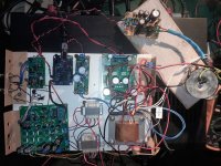
Id like to connect the I2SoverUSB interface module to a CS8414->AD1865 board (see picture below)
The "lazy" approach would be connecting the SPDIF output from the I2SoverUSB to the SPDIF input on the DAC board, although my understanding is that I could bypass/remove the CS8414 and drive the AD1865 directly from the I2SoverUSB. Has anyone any experience with it?
Look at the AD1865 datasheet. Find the input pins, connect them to the I2Sover USB output pins using 22-33ohm resistors, keeping the connection as short as possible. Don't forget to connect GND!
It should work
CS8414 -remove from socket
It should work
CS8414 -remove from socket

Thank you for the suggestion Zoltan,
I also found this, which is very helpful
I also found this, which is very helpful
so, the JLSounds interface arrived and I just try it.

On the bench, it works fine.
anjump123, I appreciate your suggestion!
Now I'm looking at other threads to learn what to put on the output. I've always used Lundahl interstage transformer (the 200 Ohm I/V resistor on the transformer legs, no cap), with success, but on this one I will not use transformer and no tube output amp.
I was not working with opamps since ... do not know, long time ago. I have no idea what is good nowdays. I will need two stage. One after the I/V resistor, than a volume pot, than...
Hello,
Thank You for this thread. I am also on the same stuff with AD1865. I have I2SoverUSB, but I have also tried the same excelent UAC EVO II. Both are great.
Now I play AD1865 with SPDiF output through CS8414 what limits me a bit. Theoretically it should play with 96 kHz, but I need to set maximum 48 kHz, if I set 96 kHZ or higher DAC is not playing.
Did you experience this as well?
I want to check I2S output. I read manual and I think I know what am I doing 😉 But hence it is my first project, could you guys confirm, that I will not destroy it?
And Can I set im my system 32 bit/386 kHz and anyway it will convert signal to 18 Bits?
Here is the "block scheme"

Would be ok?
By the way, it play excellent, no single hum or something. I just want to pass through CS8414, maybe just to try, or just because I think it could lower the potential.
Thanks for a feedback,
Piotrek
Thank You for this thread. I am also on the same stuff with AD1865. I have I2SoverUSB, but I have also tried the same excelent UAC EVO II. Both are great.
Now I play AD1865 with SPDiF output through CS8414 what limits me a bit. Theoretically it should play with 96 kHz, but I need to set maximum 48 kHz, if I set 96 kHZ or higher DAC is not playing.
Did you experience this as well?
I want to check I2S output. I read manual and I think I know what am I doing 😉 But hence it is my first project, could you guys confirm, that I will not destroy it?
And Can I set im my system 32 bit/386 kHz and anyway it will convert signal to 18 Bits?
Here is the "block scheme"
Would be ok?
By the way, it play excellent, no single hum or something. I just want to pass through CS8414, maybe just to try, or just because I think it could lower the potential.
Thanks for a feedback,
Piotrek
Attachments
hi guys,
Just an update - Yes, it works. I've contacted Lyuben from JLSounds just to make sure, cause my AD1865 is original NOS and I didn't want to lose it.
I had to unsolder resistors that was connecting 74AHC125/74HCU04 with AD1865. Simple swithing them off from power wasn't enough.
Now AD1865 is connected through I2S with I2SoverUSB (+ GND) and it works very well.
From my observation through I2S sound is more bright and detailed and through SPDiF is warmer.
Both way it works very well, Complete silence when my amp is on full power.
Hi,Look at the AD1865 datasheet. Find the input pins, connect them to the I2Sover USB output pins using 22-33ohm resistors, keeping the connection as short as possible. Don't forget to connect GND!
It should work
CS8414 -remove from socket
I've connect it directly to propper pins. It worsk. But I would like to ask why You suggest to connect it through 22-33 Ohm resistors? How it can benefit?
Much appreciate the feedback,
Merry Christmass, Peter 🙂
hi, Do you have guys recommendation where in the best way to connect GND from the USB receiver to DAC board?
Best to power I2SoverUSB from two isolated 5v power supplies. If like many people, you may find find the sound considerably more to your preference that way. Also, better to come out of I2SoverUSB using I2S bus rather than SPDIF, as SPDIF will add unnecessary jitter.
If using I2S bus to connect to the dac board, one dedicated ground wire should be run for each of the I2S signals. If using separate wires instead of coax cables, the perhaps try loosely twisting each I2S signal with its dedicated ground wire. Then separate the twisted pairs a bit from each other to to minimize chances of too much radiated cross-coupling. Ground should be connected to the dac board ground plane VERY close to where the I2S signals are connected. The I2S grounds will ground the USB board to the dac board okay. Also, in cases where an MCLK signal may be needed from the I2S board, wire it up as done with the I2S signals.
If using I2S bus to connect to the dac board, one dedicated ground wire should be run for each of the I2S signals. If using separate wires instead of coax cables, the perhaps try loosely twisting each I2S signal with its dedicated ground wire. Then separate the twisted pairs a bit from each other to to minimize chances of too much radiated cross-coupling. Ground should be connected to the dac board ground plane VERY close to where the I2S signals are connected. The I2S grounds will ground the USB board to the dac board okay. Also, in cases where an MCLK signal may be needed from the I2S board, wire it up as done with the I2S signals.
Last edited:
thank You @Markw4 .
First part I did as you suggested. I am also usying I2S output. Regarding the GND, should I use all PINS 10, 12, 14 and 16? And all of them connect to the DAC board? Can I put them together in one point?
Pins 9, 11, 13 and 15 are propely conneted to the DAC chip as I mention in post #4

First part I did as you suggested. I am also usying I2S output. Regarding the GND, should I use all PINS 10, 12, 14 and 16? And all of them connect to the DAC board? Can I put them together in one point?
Pins 9, 11, 13 and 15 are propely conneted to the DAC chip as I mention in post #4
- Home
- Source & Line
- Digital Line Level
- XMOS board interface with AD1865