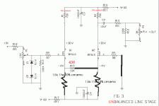
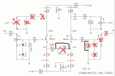
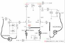
This will work but you'll get better results if you retain the gate stopper and connect to ground through a similar resistance as the i/p mosfet. Differential amps achieve best CMRR when both inputs are driven by equal impedances. Also may be a good idea to retain the trimpot.
cheers
peter
cheers
peter
Thanks, but could you perhaps draw that in on my schematics, cause I don't understand all of this !!!
Only a few more modifications and you would have a Bride of Zen ?
Why all that trouble, i would go for a BOZ right away if only unbalanced is needed.
Gr,
Nick
Why all that trouble, i would go for a BOZ right away if only unbalanced is needed.
Gr,
Nick
Electro-Nick said:Only a few more modifications and you would have a Bride of Zen ?
Why all that trouble, i would go for a BOZ right away if only unbalanced is needed.
Gr,
Nick
Cause I think, the balanced, is better as unbalanced, than the BOZ
Referring to the schematic in the first posting, seeing the Q2 drain signal is just an inverted but equal amlitude version of Q1 drain signal, it doesn't appear that Q2 is really doing anything besides making the schematic look pretty. You could probably just take the signal from Q1 drain and throw Q2 and it's extra pieces away! The total source resistance may need to be altered because there is now only half the current in it.
Circlotron said:Referring to the schematic in the first posting, seeing the Q2 drain signal is just an inverted but equal amlitude version of Q1 drain signal, it doesn't appear that Q2 is really doing anything besides making the schematic look pretty. You could probably just take the signal from Q1 drain and throw Q2 and it's extra pieces away! The total source resistance may need to be altered because there is now only half the current in it.
Using only half would yield a Bride of Zen for all
intents and purposes.
Looking at the first post again, though, I see a
Source-follower (Q1) driving the Source of a
common-Gate stage (Q2) to give a non-inverting
configuration.
It might sound a little different from a Bride of
Zen, but I can't say from experience: I haven't had
the time to build the balanced Zen linestage yet.
(The fact that I've been really pleased with my BoZ
all this time hasn't added any particular urgency,
either.) 😉
Erik
If we manage to remove R1, too, from the originally-posted schematic (single-ended input and output), we could beat the Miller effect and so improve the input rolloff frequency.
JH
JH
The way they design consumer electronics.
Just keep on snipping out parts till it stops working, then go back one. 😉
Just keep on snipping out parts till it stops working, then go back one. 😉
- Status
- Not open for further replies.
- Home
- Amplifiers
- Pass Labs
- Would this work


