Hi,
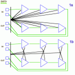
each diagram has 6 amplifiers, three on each channel.
Are they cascaded opamps/discrete and/or power?
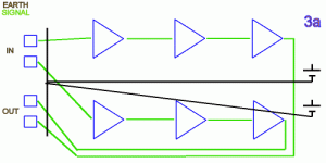
Re the Black earth line on the left of diagrams 1 & 3.
Is that the PSU common connecting the smoothing capacitors together?
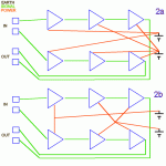
each diagram has 6 amplifiers, three on each channel.
Are they cascaded opamps/discrete and/or power?
Re the Black earth line on the left of diagrams 1 & 3.
Is that the PSU common connecting the smoothing capacitors together?
Discrete: valves within a pre-amp.AndrewT said:each diagram has 6 amplifiers, three on each channel.
Are they cascaded opamps/discrete and/or power?
It is a wire threaded through the RCAs. (I could've drawn it a little more clearly )Re the Black earth line on the left of diagrams 1 & 3.
Is that the PSU common connecting the smoothing capacitors together?
BTW, the voltage sources shown are meant to be the final power supply caps.
It's a complex subject. Before deciding, consider having a read...
http://rane.com/note151.html
http://www.tcaas.btinternet.co.uk/jlhearthing.htm
http://sound.westhost.com/earthing.htm
http://www.dself.dsl.pipex.com/ampins/balanced/balanced.htm#7
http://rane.com/note151.html
http://www.tcaas.btinternet.co.uk/jlhearthing.htm
http://sound.westhost.com/earthing.htm
http://www.dself.dsl.pipex.com/ampins/balanced/balanced.htm#7
I was just about to post a question as you replied, Gordy, and then I'll study your links, ta.
I have created a chassis with the power supply in one corner and the input stage in the other. It made sense at the time. Now I can't decide whether to send the sensitive input stage grounds on a long trip across the chassis to the final filter capacitor or instead make the star ground point at the RCAs.
Further, as I have separate rails for different stages, I am trying to decide which final cap to make the star point or whether to make two stars, each for their respective stages, or to connect all to the RCAs instead.
Think about where all the individual currents will flow, both signal and supply. Don't use GND symbols, make a drawing with all current loops completed. Then try to only route one current through any length of wiring (don't share paths for signal and power GND currents, eg); that is, seperate the loops. Treat every length of wire as if it were a resistor/inductor. Then, use twisted pair to keep loop area (inductance) of each current loop as small as possible. Use apropriate wire gauges for the power stuff (isn't that important for tube gear, though). Use shielded cable (not necesserily terminated on both ends) for the high impedance nets.
Some further references:
http://www.analog.com/UploadedFiles/Application_Notes/135208865AN-202.pdf
http://www.analog.com/UploadedFiles...14948960492698455131755584673020828AN_345.pdf
http://www.analog.com/UploadedFiles/Application_Notes/428462123AN346.pdf
http://www.analog.com/UploadedFiles/Application_Notes/41727248AN_347.pdf
Regards, Klaus
- Status
- Not open for further replies.
- Home
- Amplifiers
- Power Supplies
- Wiring and grounding options