On another thread, there was some discussion of Unity horn beamwidth and how that impacts the quality of the sound.
I've spent far too much time thinking about this stuff, so I thought I'd throw together a thread documenting some of the things that I've found.
When I rented the Danley SH50s, I found that they sound a lot like a giant pair of headphones. The experience is very much like listening to headphones - you get a really pinpoint soundstage. Probably more than any speaker I've ever heard.
The pinpoint sound is because the beamwidth of the SH50 is relatively narrow, and the horn controls the beamwidth down to below 500Hz.
The pinpoint nature of the speakers can be a blessing and a curse. For instance, with well recorded music, the definition of the soundstage is wonderful. With poorly recorded music, it can be a bummer that everything sounds like it's mono. This isn't a fault of the loudspeaker, it's a fault of the recording. But let's be realistic; speakers that 'throw' a lot of sound into the sidewalls can create a sense of spaciousness that's artificial, but euphonic.
I've seen people building Unity horns on diyaudio, and I've noticed that sometimes people are picking wall angles arbitrarily.
IE, sometimes people are setting the walls at 75 degrees or even 90 degrees. I'm guilty of this myself; my most famous Unity horn project, from way back in 2006, used an angle of about 100 x 60.


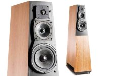
Here's the Lambda Unity Horn, from back in the day. 60 x 60 degrees iirc.

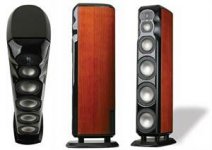
Here's a Danley SH50


This morning, I made this 3D model of it, to illustrate my point.
IE, sometimes people are setting the walls at 75 degrees or even 90 degrees. I'm guilty of this myself; my most famous Unity horn project, from way back in 2006, used an angle of about 100 x 60.
Here's the Lambda Unity Horn, from back in the day. 60 x 60 degrees iirc.
Here's a Danley SH50
This morning, I made this 3D model of it, to illustrate my point.

Using the same dimensions as the SH50, you'll notice a few things:
1) Top to bottom, the midrange taps are 8.5cm away from each other
2) Left to right, the midrange taps are 8.5cm away from each other
1khz is 34cm long. One quarter wavelength of 34cm is 8.5cm.
I don't know what the crossover point of the SH50 is. I'm willing to bet it's about (you guessed it) 1khz.
In some of the DIY Unity horn designs, I've noticed a tendency to put the midranges as close to the throat as possible, and ALSO a tendency to pick the wall angles arbitrarily. I don't think this is a great idea, because the angle of the walls tends to dictate the location of the midrange taps, and the location of the midrange taps tends to dictate the angle of the walls.
In other words, the more you widen the walls, the closer you have to bring the midranges towards the throat. Eventually you get to a point where it's not possible to get the midranges close enough. If you reach that point, your only real solution is to use a horn with a narrower angle, or find a compression driver that can live with a REALLY low xover point. (We'll get to that in a minute.)
I don't know what the crossover point of the SH50 is. I'm willing to bet it's about (you guessed it) 1khz.
Hi Patrick,
crossover point between mids and HF in SH50 is 1.3khz.
I'm not grasping your point(s).
What do you consider a wide beamwidth Unity?
Why would one be hard to build ?
(For me, wide is 90 deg or greater horizontal, which I've found to be easier to build than narrower designs.)
And why would you say people pick wall angles arbitrarily?
All the Unity/Synergy/MEH threads I've read indicate folks deliberate over wall angles quite carefully.
And also mouth size for how low they want pattern control.
(I know I do, very much so, to be able to make comparisons.)
Okay, here's the main point of this thread, and another piece of the puzzle that I think isn't immediately obvious:
You can arrange the drivers in such a way, that you have flat frequency response, well behaved phase response, but the drivers themselves are as much as 25-35cm from each other.
I've been listening to loudspeakers at home and at audio shows for the better part of 30 years, and less than five speakers I've ever seen do this trick.
Even the best conventional loudspeakers generally have all their drivers mounted on a vertical line. And there's nothing wrong with that, you can definitely achieve flat frequency response, and with some careful massaging of the crossover, you can get well behaved phase. Vandersteen speakers were my reference for two years, and they also have that 'neat' ability to be really articulate, that Unity horns do so well.
But none of those speakers do this weird 'trick' where it's exceptionally difficult to tell where the soundstage begins and ends. I've told this story a hundred times: when I rented a set of SH50s, our teenage daughter asked me if they were turned on! IE, it's so hard to locate where the speaker is, acoustically, she literally couldn't be sure that they were playing or not, and she was seated less than a meter from the speaker!
Attachments

Here is some collection about the "rules": Please Critique my multi-entry horn simulation post #4. I haven't checked if they are Tom Danleys amusings or someone elses.
There is mention that two things affect the position of midrange taps: distance from the compression driver should be 1/4 WL or less and circumference of the horn at that point should be no more than 1 WL for the reason unkown to me. Now if you have say 4" mid drivers, you get them only that close to the throat, say 2.5" if the tap is in the middle of the driver. Now the circumference at that point should be 10" or less and this limits the beamwidth.
I tried Bill Waslo synergy calc spreadsheet and it shows the area at the taps when the beamwidth and other variables are manipulated so the following insights are from based on a flat sided conical waveguide like SH50. A 10" circumference would translate roughly to an area of 50cm2 (area of circle) and this requires conical waveguide with about 47x47deg beamwidth, pretty narrow! I've got no idea what happens if this "requirement" is not met but the SH50 being 50x50 beamwidth approximately follows this rule. The rule probably provides the bandpass charasteristics just about right for making passive crossover "easy".
Assuming the circumference rule is to be obeyed one could have wider beamwidth if the taps are closer than 1/4 WL to the throat. Doing so could make passive crossover hard task but with DSP there shouldn't be any issue. To get taps closer to throat: offset the tap from the mid driver center closer to throat or use a coaxial compression driver, or just a modern compression driver which plays lower, or maybe with some other horn profile than straight sided conical. All these options have some trade-offs 🙂
Last edited:
I'm not grasping your point(s).
What do you consider a wide beamwidth Unity?
Why would one be hard to build ?
(For me, wide is 90 deg or greater horizontal, which I've found to be easier to build than narrower designs.)
And why would you say people pick wall angles arbitrarily?
All the Unity/Synergy/MEH threads I've read indicate folks deliberate over wall angles quite carefully.
And also mouth size for how low they want pattern control.
(I know I do, very much so, to be able to make comparisons.)
Here's a 50x50 Unity horn, modeled after the dimensions of the Danley SH50. Midrange taps are 8.5cm apart, top to bottom and left to right.
If you use a crossover frequency of 1khz, then the midrange taps are within one quarter wavelength of each other, because 1khz is 34cm long and one quarter of that is 8.5cm.
Lament said that the crossover frequency if 1.3khz. That's one third of a wavelength, or right about the point where we're going to start to get destructive interference.
Destructive interference happens when two sources are too far apart, of course.
For instance, if you have midrange taps that are 8.5cm apart from each other, top to bottom, and a crossover point of 2khz, then you're going to have one midrange cancelling out the OTHER midrange, because the pathlength difference between the two is 1/2WL. (And 1/2WL generates a deep null.)

If we increase the angles of the walls from 50x50 to 90x60, we get something like the horn pictured above.
Now that the wall angles are wider, the distance from top to bottom and from left to right is larger. The distance from top to bottom is 10.5cm and the distance from left to right is 13.3cm.
The increase in the distance between the midrange taps means you need to lower the crossover frequency now. For instance, a distance of 10.5cm would lead you to a crossover of 800Hz and a distance of 13.3cm would get you a crossover of 639Hz.
If you're a wizard with these things, like Danley, you could probably push that crossover as high as 944Hz. But that's still quite low for a compression driver.
The geometric relationship between the angles of the walls, the crossover point, the distance from the throat, etc... All of these variables tend to encourage a designer to use a beamwidth of around 50-60 degrees.
Of course, the Danley SH96 has a wall angle of 90x60 degrees.
To pull that off, they had to use a larger and more expensive compression driver.
Something that I should stress here, is that I'm hardly the authority on these things. For instance, the reason I know that widening the walls can lead to heartbreak is because I found out the hard way. In particular, I was doing polar measurements on a Synergy horn project of mine, and I found that the beamwidth became very narrow in the midrange.
This is A Very Bad Thing and it basically defeats the entire purpose of building a Unity horn: what's the point of going to all this hassle, just to have screwed up midrange polar response?
What was happening in that design of mine, was that I'd made the walls too wide, and I couldn't get the mids any closer to the throat. So I had to dump it in the trash. The only other alternative would have been to use a larger compression driver, but that was ALSO a no-go, because it would have required me to build a new horn.
Attachments
Here is some collection about the "rules": Please Critique my multi-entry horn simulation post #4. I haven't checked if they are Tom Danleys amusings or someone elses.
There is mention that two things affect the position of midrange taps: distance from the compression driver should be 1/4 WL or less and circumference of the horn at that point should be no more than 1 WL for the reason unkown to me.
Here's an illustration, explaining the "one wavelength rule."

It's basically a shortcut to figure out what the xover should be, without busting out your calculator. Because the taps should be about 1/4WL apart, and the four sides of the horn add up to... one wavelength.
So even if your horn is asymmetric, adding up the sides will get you the number you're looking for, without having to resort to doing the math for the X and the Y axis.
Of course, this assumes that your waveguide is relatively symmetrical. That shorthand wouldn't work for a horn that's much wider than it is tall, or vice versa.
Hi Patrick,
Cool, thanks for the well laid out reply.
I guess the reason I still have a problem with it, is that synergies don't have to follow a physical layout formula...there's so many ways to mount drivers other than the norm.
Depending on method, narrow can be tougher than wide, or vice versa.
There's also no need to use 4 small mid drivers, or X number of any driver, save maybe one CD 🙂, for our simple home type builds.
Imho, simply adhering to 1/4 WL spacing is 90+ % of the game in a syn.
So many things seem to tie us in knots, that just ain't that important, ...or so i keep measuring and hearing. my 2c.
I completely agree how using a CD that will reach low, makes everything so much easier.
Honestly, given the time, effort, cost of mistakes, re-dos, complexity of separate small mid-to-woofer bridge drivers ... well...it almost seems a bargain to bite the bullet and get a low reaching CD and skip all that crud.
You know the old adage in prosound, buy once - cry once. 😉
Hi Patrick
I recently tried jumping in the Unity/Synergy/MEH pool after spending a lot of time reading Syntripp, Cosyne and other threads where you Bill Waslo, Weltersys and xrk971 were all contributing (amoung others).
I’d like to know if I’m wasting my time with what I’m trying to work with and my obviously limited understanding.
I really wanted to try and maintain a point source with good sensitivity that would give me better directivity (less beaming) than the 8 inch fullrange drivers I was using in Oris front horns.
I discovered I was tired of their very small “headphone” sweet spot when I started playing with OB after my Oris got knocked over and damaged.
I thought I would pursue Bill’s Cosynene because it seemed the best documented.
The CD and Gento drivers were easy to get. I was going to try and go active so I could use the the 4 Ohm version of the Aura woofers that were still available.
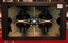
Then I discovered some fairly big B52 (90 X40) conical buyout horns at Parts Express.
TE-8180 1" Horn 22.5" x 10" 1-3/8"-18 TPI
I thought the 90 degree horizontal dispersion would work better to broaden the sound stage and that I could make my life easier with them by modifying them (rather than building from scratch) like some other projects (Small Syns).
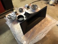
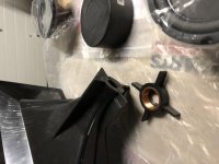
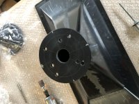
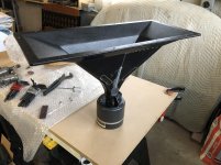
I’m pretty much at a stand still after having modified one horn to bolt up the Celestion and a Dukane 5A540 I had.
There doesn’t seem to be enough room for the Gentos and the Aura woofers.
I thought maybe I could go 2 way with just the Aura and the Dukane CD which can go down to 500Hz and cross probably around 800Hz (I was hoping).
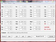
I tried some reverse engineering by taking physical measurements of the B52 horns and inputting them into hornresp.
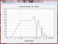
My modeling in hornresp with the Auras shows a big spike right before they crash just short of 1KHz. The only way I can get decent response down near 200Hz is to model them in a larger vented back chamber.
I specified a very short back chamber, as Bill did with the Cosynene, to negate back chamber reflections in the model.
I actually have some other Aura NS35 I also tried modeling...they give me pretty much the same results.
I have some B&C 8pe21 I modeled which look better, but they’re too big to mount on these horns.
I was using the same woofer port size for the Auras that Bill recommended in his Cosynene article.
I don’t think I can get the woofer ports in the same location (in relation to the throat) that Bill had on this smaller horn. They would have to be about an 3/4 -1” further away if I want to bond my PVC driver mounts on the flat part of the second expansion.
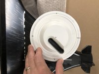
I made some fillers to reduce volume under the woofer cone with the hope of extending or pushing the upper frequency response spike further up.
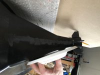
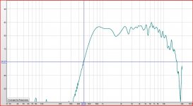
I also mounted up the Dukane to the modified horn without the woofer ports and measured it in my living room with REW to see what it would do. I could only center it floor to ceiling, set the mic a meter away and use a gated measurement.
I get the feeling I’m trying to put a square peg in a round hole.
I recently tried jumping in the Unity/Synergy/MEH pool after spending a lot of time reading Syntripp, Cosyne and other threads where you Bill Waslo, Weltersys and xrk971 were all contributing (amoung others).
I’d like to know if I’m wasting my time with what I’m trying to work with and my obviously limited understanding.
I really wanted to try and maintain a point source with good sensitivity that would give me better directivity (less beaming) than the 8 inch fullrange drivers I was using in Oris front horns.
I discovered I was tired of their very small “headphone” sweet spot when I started playing with OB after my Oris got knocked over and damaged.
I thought I would pursue Bill’s Cosynene because it seemed the best documented.
The CD and Gento drivers were easy to get. I was going to try and go active so I could use the the 4 Ohm version of the Aura woofers that were still available.
Then I discovered some fairly big B52 (90 X40) conical buyout horns at Parts Express.
TE-8180 1" Horn 22.5" x 10" 1-3/8"-18 TPI
I thought the 90 degree horizontal dispersion would work better to broaden the sound stage and that I could make my life easier with them by modifying them (rather than building from scratch) like some other projects (Small Syns).
I’m pretty much at a stand still after having modified one horn to bolt up the Celestion and a Dukane 5A540 I had.
There doesn’t seem to be enough room for the Gentos and the Aura woofers.
I thought maybe I could go 2 way with just the Aura and the Dukane CD which can go down to 500Hz and cross probably around 800Hz (I was hoping).
I tried some reverse engineering by taking physical measurements of the B52 horns and inputting them into hornresp.
My modeling in hornresp with the Auras shows a big spike right before they crash just short of 1KHz. The only way I can get decent response down near 200Hz is to model them in a larger vented back chamber.
I specified a very short back chamber, as Bill did with the Cosynene, to negate back chamber reflections in the model.
I actually have some other Aura NS35 I also tried modeling...they give me pretty much the same results.
I have some B&C 8pe21 I modeled which look better, but they’re too big to mount on these horns.
I was using the same woofer port size for the Auras that Bill recommended in his Cosynene article.
I don’t think I can get the woofer ports in the same location (in relation to the throat) that Bill had on this smaller horn. They would have to be about an 3/4 -1” further away if I want to bond my PVC driver mounts on the flat part of the second expansion.
I made some fillers to reduce volume under the woofer cone with the hope of extending or pushing the upper frequency response spike further up.
I also mounted up the Dukane to the modified horn without the woofer ports and measured it in my living room with REW to see what it would do. I could only center it floor to ceiling, set the mic a meter away and use a gated measurement.
I get the feeling I’m trying to put a square peg in a round hole.
Attachments
-
 87F2394A-08DB-499F-83A6-6FBED20818E5.jpg992.5 KB · Views: 221
 -
 FC3048D9-BCC1-4401-94C0-C23270729355.jpg701.8 KB · Views: 214
 -
 4BBBD8D9-B45F-48B0-BCA8-8BB6FB9A411C.jpg984.9 KB · Views: 215
 -
 044BE7BB-A1AE-43C3-90D2-536F42B1EFD1.jpg791.9 KB · Views: 217
 -
 88B8C23E-B228-4D0D-9EB8-EE715565AA40.jpg678.8 KB · Views: 239
 -
 43888EDC-CD19-4105-8F59-649293DFD952.jpg721.4 KB · Views: 154
 -
 4F13C9A3-A724-4284-9272-84574566ACD7.jpg988.2 KB · Views: 195
 -
 EE05900B-5ED6-4C90-8B8D-974E7EA552B1.jpeg67.7 KB · Views: 161
 -
 BAD66C4C-65AE-4489-9082-EC29CDC2482D.jpeg55.4 KB · Views: 147
 -
 ECE22DCD-CFEC-4446-9E18-C323357816A6.jpeg84.1 KB · Views: 168
Imho, simply adhering to 1/4 WL spacing is 90+ % of the game in a syn.
So many things seem to tie us in knots, that just ain't that important, ...or so i keep measuring and hearing. my 2c.
I completely agree how using a CD that will reach low, makes everything so much easier.
Honestly, given the time, effort, cost of mistakes, re-dos, complexity of separate small mid-to-woofer bridge drivers ... well...it almost seems a bargain to bite the bullet and get a low reaching CD and skip all that crud.
You know the old adage in prosound, buy once - cry once. 😉
A common theme with nearly all of my projects, has been an attempt to go the *other* way, basically trying to push the crossover point higher so that I can accommodate more "hi-fi" tweeters. For instance, my latest project uses a planar tweeter (Ribbon Unity Horn)
The struggle for me, has always been trying to tame the high frequency behavior.
You can make a compression driver sound good, but dollar for dollar, it's tough to beat direct radiating tweeters.
Patrick: Good description of the SH50 "big headphones", I get much of that with my modded Yorkville Unity U15. It's the only pair of horns I've had, and no plans to change that after five years 🙂
bradleypnw: that's an interesting idea, but as I explain below, I think you'd run into the problem of unpreditable wave launch from the DML. Ideally a horn puts out a smooth plane wave (?), the DML would, I think unpredictably bounce waves in many directions, riccocheting down the horn walls which would cause unpredictable sound. Who knows? It might be interesting to try, it certainly breaks all the rules.
Tmuikku, I am pretty sure the circumference = 1 wavelength rule is for the following:
In a conical horn this is the ideal expansion location for a wavelength at that frenquency f.
I think it, stated another way, is that the mid (in this case) port should be at that circumference or smaller, than the highest frequency it will pass. This insures that the wave that forms "launches" from the proper part of the horn (depends on that circumference.) If you went higher in frequency than proper, you will get multiple path issues (beaming?)
Last edited:
- Home
- Loudspeakers
- Multi-Way
- Why It's Hard to Have Unity Horns With Wide Beamwidth