Hi,
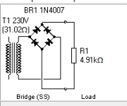
I have a newby question which is confusing me here. I modeled the attached transformer, bridge rectifier, and load resistor in PSUD2 and it says the voltage across R1 should be 321 volts. I did not any filter caps yet.
So I bread boarded this circuit exactly as shown, applied my 230 volts transformer to the bridge rectifier, added a 100W load resistor I had of 4,191 ohms. But when I measure the voltage across R1 on the bread board I get only 204 volts? How could my circuit be so far off from the 321 volts PSUD2 says I should be getting? Am I measuring the voltage wrong?
Rick
Attachments
Last edited:
You need a large filter capacitor across the load to raise the voltage to the peak value.
The peak is 230V x sqrt 2 = 325V. Right now, you're measuring a rectified sine with Vrms = 230V.
Try AC volts on your meter if it can measure true rms, since this is not a DC voltage.
If your meter measures only average voltage, it will be around 11% less, or 207V.
The peak is 230V x sqrt 2 = 325V. Right now, you're measuring a rectified sine with Vrms = 230V.
Try AC volts on your meter if it can measure true rms, since this is not a DC voltage.
If your meter measures only average voltage, it will be around 11% less, or 207V.
Last edited:
You need a large filter capacitor across the load to raise the voltage to the peak value.
The peak is 230V x sqrt 2 = 325V. Right now, you're measuring a rectified sine with Vrms = 230V.
Try AC volts on your meter if it can measure true rms, since this is not a DC voltage.
If your meter measures only average voltage, it will be around 11% less, or 207V.
Thank you so much I was pulling my hair out. I'll build out the rest of the filter train to get things down to DC.
I'll build out the rest of the filter train to get things down to DC.
Watch carefully for the polarity of the electrolytic capacitor, or it could explode.
The positive capacitor terminal must go to the junction of the two diode cathodes.
On your drawing, that is the top end of the resistor. Use at least a 10uF, 400VDC capacitor.
More info:
https://www.electronics-tutorials.ws/diode/diode_6.html?nab=0&utm_referrer=https://www.google.com/
Last edited:
Watch carefully for the polarity of the electrolytic capacitor, or it could explode.
The positive capacitor terminal must go to the junction of the two diode cathodes.
On your drawing, that is the top end of the resistor. Use at least a 10uF, 400VDC capacitor.
More info:
https://www.electronics-tutorials.ws/diode/diode_6.html?nab=0&utm_referrer=https://www.google.com/
Thanks rayma, can't be too careful
...How could my circuit be so far off from the 321 volts PSUD2 says I should be getting?...............
You explicitly, and admittedly, did not build the thing you showed to PSUD.
Try again as-built, withOUT the cap. Or since PSUD "knows" that would be stupid, try with a small bad cap.
The output is NOT steady. How a practical "DC meter" reads this can vary. Your 204V is in-sight of Mean and RMS values. It's not wrong. It is a lesson.
Attachments
You explicitly, and admittedly, did not build the thing you showed to PSUD.
Try again as-built, withOUT the cap. Or since PSUD "knows" that would be stupid, try with a small bad cap.
The output is NOT steady. How a practical "DC meter" reads this can vary. Your 204V is in-sight of Mean and RMS values. It's not wrong. It is a lesson.
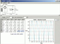
Oh man I feel stupid. This is the first time I've used PSUD2 and didnt see the other columns on the left! I had to drag the frame bar over to uncover them, sheesh. If only I had seen that earlier.
Yes, my Fluke is reading exactly the Mean value. I have the whole thing bread boarded now ready to measure what ripple I have.
The average rectified voltage without a filter cap is 2/π times the peak value with a filter cap.
321V peak has an average of 204V, agreeing exceptionally well with your measurement.
321V peak has an average of 204V, agreeing exceptionally well with your measurement.
- Home
- Amplifiers
- Power Supplies
- Why is my bridge rectifier voltage low here?