Or, is it- which switch is which?
The switch shown below is for my AR XA reworked/rebuilt/super-duper turntable. The switch is used to turn the motor off and on.
Using the diagram shown just below the words, the switch (C-2), is wired as shown below. The light does not work on the switch and I also get a pop when turning off the switch.

Anybody know how to wire the switch as shown on the switch?

I'm thinking to myself that hot goes to the center prong, neutral wire with pigtail goes to the other two prongs?
Looks like a capacitor (what value?) and resistor in series??
Enquiring mind wants to know (me). I know I can just wire it all up thusly, but thought to myself that old turntable questions should have responses from some of the DIY gurus.
Thanks,
Dan
The switch shown below is for my AR XA reworked/rebuilt/super-duper turntable. The switch is used to turn the motor off and on.
Using the diagram shown just below the words, the switch (C-2), is wired as shown below. The light does not work on the switch and I also get a pop when turning off the switch.
Anybody know how to wire the switch as shown on the switch?
I'm thinking to myself that hot goes to the center prong, neutral wire with pigtail goes to the other two prongs?
Looks like a capacitor (what value?) and resistor in series??
Enquiring mind wants to know (me). I know I can just wire it all up thusly, but thought to myself that old turntable questions should have responses from some of the DIY gurus.
Thanks,
Dan
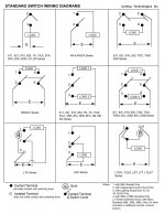
FYI, the "capacitor" is actually the symbol for a neon lamp... It would have resistor in series to limit the current and brightness.
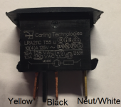
From your photo, I believe that the left terminal goes to the Black wire, the middle terminal goes to the yellow wire, and the right terminal goes to the white wire.
From your photo, I believe that the left terminal goes to the Black wire, the middle terminal goes to the yellow wire, and the right terminal goes to the white wire.
Thank you.
Black wire being hot, yellow wire being neutral, white wire pigtailed off the neutral? I'll give it a whirl later today.
I appreciate all the answers!

Black wire being hot, yellow wire being neutral, white wire pigtailed off the neutral? I'll give it a whirl later today.
I appreciate all the answers!
But it says 'capacitor' on the schematic, and it is consistent with a run-up capacitor for this type of motor. It's even selected for that particular motor.FYI, the "capacitor" is actually the symbol for a neon lamp...
There is of course a no-brainer check if the switch is bad: just connect the two wires going to the switch together. If it works, get a new switch.
Jan
It looks like Yellow is hot connected to switch and Black. White is neutral connected to Red and capacitor.
Sorry if I wasn't clear, but I was referring to the schematic that's printed on the switch, not the schematic of the turntable....But it says 'capacitor' on the schematic, and it is consistent with a run-up capacitor for this type of motor. It's even selected for that particular motor.
There is of course a no-brainer check if the switch is bad: just connect the two wires going to the switch together. If it works, get a new switch.
Jan
You could make it safe and switch both L and N with a DPST switch. A good habit. No possible feedback anymore (think of the cap).
Or be smart.
1) Remove the two wires from the unit to the switch and connect them together, together to see if the unit itself works.
If that's OK, proceed to 2).
2) Next, with an ohmmeter, check which switch pins are connected together or open in each switch position.
If there's no combinations that gives connected pins, the switch is toast.
If you find a position where two switch pins are connected in one and open in the other switch position, proceed to 3).
3) Select the correct switch pins to connect the wires from the unit to, so they are connected in the switch 'on' position.
Done.
Did I tell you guys I hate blind trial and error?
Jan

Just the DMM in resistance mode should be enough. At least to be able to switch the turntable on/off.
We’ll deal with the neon lamp next week 😉
We’ll deal with the neon lamp next week 😉
Last edited:
Just to clarify the switch situation:
The switch is a new Carling Technologies LRA211C.
I am replacing it because the old switch, which was the same make and model number popped when turning off, and the light has never worked.
I loaded down a copy of the wiring diagram as shown in post #7.
Connected the wires as shown on the diagram. The switch turns the motor on/off, but there is a popping sound from the speakers when switching the turntable off, and the light does not work. I can connect the hot wire to the opposite side of the switch (shown with the black wire on diagram, post #7) and the neutral wire (shown as yellow wire on the diagram), and the light works when switched on, but the motor doesn't start spinning.
The only info I have on connections for the switch are on the switch itself. The datasheet is worthless for me, but I don't claim to be an electronic guru or technician.
So, I will buy a DPST switch, witch I hope has a proper wiring diagram, so that I can solve the popping/no light switch problem.
- Home
- Source & Line
- Analogue Source
- Which switch is which?