Hi Guys,
I'd like to do some pcb stators for a new project. I found that the usual pcb design software is a pain to design the boards as they are circuit and component oriented. I admit I'm no expert at pcb design so perhaps there are tricks to get it done, but I'm not versed enough to work with the software outside of the box.
A stator board would be not much more than a copper fill with some blank area's and lots and lots of holes. What would be a good way to make such an design? It needs to have Gerber output to be send off to a pcb manufacturer.
Thanks for your suggesions!
Sprint-Layout is cheap and an excellent PCB package. It's as easy to use as Paint too. You should be able to do what you want using the Zone function I reckon.
I use Traxmaker (Circuitmaker2000) for laying out such designs.
You can draw layouts freely with a resolution down to 1mil of resolution.
I used it to make the stator supports on my latest build.
I know the package is quite dated by now but it is still by far the easiest system I have ever worked with.
You can still find it on the web if you dig hard enough.
I still use it to this day.
jer 🙂
Attachments
Last edited:
i used cambam, it is not a drawing program perse, it is for cnc machines making toolpaths, and smal drawing stuff.
But it has some good options for filling in large area's with holes with ur selected spacing. im pretty certain you can use it. and its free!
you can export to dxf from there i think there are manny programs to convert it.
i dont know where you live but i also would like to make some, wondered why let them be made ?. is that not expensive ? if you are interested in trying a version on my cnc ur welcome, never dont one yet im interested to.
ps Pm me for telephone number if you want, else ill see you on the ESL days in soon 🙂
Last edited:

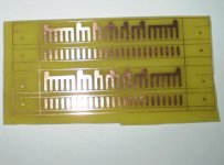
You can use Eagle to draw a polygon with holes.
Just draw a signal line in the schematic editor, give the polygon the name of the signal and use ratsnest to show your work in the top or bottom layer.
I made this in a few minutes.
That looks good. If I knew how to operate Eagle it would be a piece of cake I suppose. I did give it a try some years ago until the steep learning curve made my head explode 😀
Perhaps I should give it another try.. or pay someone to make the layout.
i used cambam, it is not a drawing program perse, it is for cnc machines making toolpaths, and smal drawing stuff.
Thanks I'll have a look!
How big of a panel are you looking to plot? I've done this for a large ESL panel, but the board house was not able to fab it because of the size.
The easiest way to do it is as a negative: Where ever there is to be a hole, polt a round pad in the copper layer with a drill that is 10mils smaller than the pad centered on it. In the gerber editor, select the copper layer and change it to a negative. The pad becomes a void and the empty space becomes copper. Because the pad (now void) is larger than the drill, the copper is not exposed at the edge of the hole. Your board house will thank you for doing this rather than trying to do a copper pour around a bunch of holes.
This also needs to be a multilayer PCB (as far as the board house is concerned). At least that is the way I intended to do it. Plot the board as a single sided copper clad PCB and have it laminated with a 10-15mil "filler" layer (FR4 with no copper on either side). This will give you the insulation needed for the HV.
Attachments
Last edited:
Thanks for the tip Pyramid, using a negative is an excellent suggestion!
Which software would you recommend for this? I'm using diptrace for my regular boards but it does not have align functionality so getting all these holes aligned would be next to impossible 😀
Which software would you recommend for this? I'm using diptrace for my regular boards but it does not have align functionality so getting all these holes aligned would be next to impossible 😀
Last edited:
- Status
- Not open for further replies.
- Home
- Loudspeakers
- Planars & Exotics
- Which software for designing PCB stators?