Greetings Friends. I've been playing around with the EL84 amp I posted about the other day and got to wondering about the total load seen by the power transformer. Obviously the tubes consume power, each power tube dissipates ~11.5w (as per RobRob calculator, 275 plate, 8.5v cathode, 200R cathode resistor, 43mA x 267v = 11.5w) and the preamp tubes eat a couple of mA. But the resistors and choke in the power supply also consume power, as do the cathode resistors. How do we reckon those loses? Is it as simple as applying Ohms law to each component and then adding up all those watts, or...?
Thanks for taking a look.
w
Thanks for taking a look.
w
I don't have a direct answer, but I find it extremely helpful to model the power supply in PSUD2. If you know how much your output tubes are pulling and can approximate fairly well what the preamp tube(s) are pulling, you just factor that into the total load in PSUD2 and the simulation will automatically factor in losses for the cap(s), resistor(s), choke(s) in the PS chain, as long as you enter that info.
So perhaps not an answer, but maybe it would get you closer to something related to your question?
So perhaps not an answer, but maybe it would get you closer to something related to your question?
Look at it from a total power draw standpoint. Measure the current being drawn by everything, and the loaded DC power supply voltage, at the FIRST cap. That gives watts consumed in the total load. The volt-amperes in the transformer is more. How much more depends on the type of filter after the rectifier. If it is a capacitor input, the factor is 1.6X. If it’s choke input it is 1.1. The power factor is higher with the choke. This is the rating needed in the transformer for continuous operation.
To figure the losses in the transformer (and choke if there is one), back the RMS current out from the VA draw. It is higher than the DC load by that “factor”. Then calculate I squared R in the choke, secondary, and primary.
The power factor is an approximation, based on typical conduction angles. Could be more, could be less than the 60-ish %. Bigger transformers with lower losses and less leakage inductance are actually worse. If it’s getting the life squeezed out of it, it is probably running 70-80% Because the conduction angle spreads. If the voltage under load sags a lot, that is what is happening. To get more accurate, you need to measure true RMS currents in the secondary, primary, and choke (if applicable). Simulations like PSUD help. Like any simulation, it’s only as good as the model and transformers as simple as they are, are hard to model accurately.
Hey, thanks for taking a look. Should have posted a schematic, but I don't have an up to date one and I'm stuck at work.
Anywho, it is a CLC power supply. I am familiar with PSUD, but not expert. Not sure how to set it up to correctly model the circuit. But I don't think PSUD's model includes any part of the circuit beyond the tubes, and the power consumed by the power tube's cathode resistors is what I'm really asking about here. I've built an amp with an over-rated PT, but this one is right at the ratings and I'm wondering if those big resistors might put me over the top. Of course, Hammond brags that their PTs are under-rated, so maybe it's nothing.
Anywho, it is a CLC power supply. I am familiar with PSUD, but not expert. Not sure how to set it up to correctly model the circuit. But I don't think PSUD's model includes any part of the circuit beyond the tubes, and the power consumed by the power tube's cathode resistors is what I'm really asking about here. I've built an amp with an over-rated PT, but this one is right at the ratings and I'm wondering if those big resistors might put me over the top. Of course, Hammond brags that their PTs are under-rated, so maybe it's nothing.
Old schematic. I've removed that 150R resistor in front of the choke.

B+ is now 308
B++ is 294
275 on plates
8.5 on cathodes
B+ is now 308
B++ is 294
275 on plates
8.5 on cathodes
Also, how do you measure current drawn? When I had that 150R resistor in front of the choke, it was simple enough to measure the voltage drop and use Ohms law to determine amps. Can I do that with the choke?
If you're already right at the limit, then go up to the next VA size.
The choke winding has 150R DC resistance, so that makes the only dissipation in the choke.
Reactive elements like L and C don't dissipate significant power as the current and voltage in them are not "in phase".
Measure the DC current by measuring the DC voltage across each 200R resistor, calculate V/200, and add them.
Last edited:

Use the ammeter part of your meter between the choke and the two 200R resistor tie points. Then read the resistance through the open choke and do Ohm's law to see if they jive.
Replace Rd with a 10 ohm resistor. Measure the voltage drop across the resistor. From the voltage drop use Ohm's law to determine the current draw of the entire amplifier.
Is it as simple as applying Ohms law to each component and then adding up all those watts, or...?
Yes, and yes. It's just Ohms at this point.When I had that 150R resistor in front of the choke, it was simple enough to measure the voltage drop and use Ohms law to determine amps. Can I do that with the choke?
All good fortune,
Chris
Not quite. the OPT has both Copper & Core Losses. These vary, depending on the size of the signal being passed.Is it as simple as applying Ohms law to each component and then adding up all those watts, or.
Figure about 15% of the audio is lost in the OPT at full power, The core losses vary as signal size & are composed of hysteresis
& eddy current losses in the lamination's. These losses have to come from somewhere & that would be the PS.
Losses in the PT are somewhat complicated, especially when cap input filter is used. The switching creates large harmonic currents
which are the cause of more heating in the PT of this kind of circuit. Bridge circuit is much better than the CT arrangement.
PT heating is a serious problem that can lead to destruction.
OK, now & do the Ohm's Law part, both Ohm & Mho will be pleased.
👍
What exactly are you trying to figure out? I think you may be confusing different concepts.
You said you already know the DC current drawn by the tubes -that tells you the total current for the amplifier. Multiply that DC number by about 1.6 to get the total AC current the transformer has to supply. Adding series resistors or chokes into the power supply does not increase the load on the transformer, in fact they reduce it because they 'restrict' the current a little more!
You said you already know the DC current drawn by the tubes -that tells you the total current for the amplifier. Multiply that DC number by about 1.6 to get the total AC current the transformer has to supply. Adding series resistors or chokes into the power supply does not increase the load on the transformer, in fact they reduce it because they 'restrict' the current a little more!
If you disconnect the choke you can measure its DC wire resistance, then measure the DC voltage drop across it in circuit, and apply Ohm's law to find the DC current.Also, how do you measure current drawn? When I had that 150R resistor in front of the choke, it was simple enough to measure the voltage drop and use Ohms law to determine amps. Can I do that with the choke?
Measure the DC voltage across the resistor then calculate the power dissipated by the resistor:the power consumed by the power tube's cathode resistors is what I'm really asking about here.
P = V2 / R
If you know the current through the resistor then you could use this formula instead:
P = I2 * R
A very useful modification puts the 10R resister in the negative lead to the PT CT.Replace Rd with a 10 ohm resistor. Measure the voltage drop across the resistor. From the voltage drop use Ohm's law to determine the current draw of the entire amplifier.
That makes checking voltage drop much safer. And a good place to check peak current
into the first cap you can see with a scope, At that point the current needs a RMS
responding meter, these daze most DVMs are. 👍
Move the 150R ( or 100R ) current sampling resister to the negative return lead to the PT CT. Use a 2W resister.I had that 150R resistor in front of the choke,
The first cap after the rectifier is better at 22 microF, less stress on the PT.
Not only does that work well but it is a safety feature if you intend to use this amp as a teaching tool.
The Hammond 270DAZ will be short lived in this circuit, there is no capacity to allow for RMS currents in the HV windings.👎
The PT is not hot to the touch, but maybe if I was running it louder...But yes, the amp is a teaching tool for the DIY club. I've removed the 150R resistor and increased the K resistors to 200R, tubes now running ~42mA so hopefully low enough to keep the PT happy
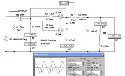
I ran an Electronics Workbench simulation of the circuit on page 5. are the voltages on your schematic actual measured?
In the Sim there are both AC & DC ammeters in the negative return lead to the PT HV CT.
If we do 'root of sum of squares' the RMS current thru the PT & rectifier is 154 mA.
The DC component goes thu the load. the AC component thru the 47 microF cap & back thru the PT & rectifier.
Pls measure the DC resistance of each half of the PT HV winding, I'll put that in the Sim. THX
Attachments
Could you explain this for us novices? Aren't these transformers designed for this?The Hammond 270DAZ will be short lived in this circuit, there is no capacity to allow for RMS currents in the HV windings.👎
- Home
- Amplifiers
- Tubes / Valves
- Where do all those mAs go? (On reckoning the total load seen by the PT)