HI
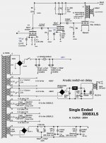
the amp is diy SE 6em7 driver eml300bxls ,psu 340v ss 100µ choke 200µ.
pw tube is 70ma, so total current 170-180ma
old choke is ll1638 4He 32ohm
new is tamura a4004 10He 120 ohm
well I have risk , the fullrange pumping a lot and If a see well ,the filament blink ie at start up with cold tube a blast of current if the trafo sag ??😱😡
thanks nick for fast help ,now I need help my to solve and learning how do a correct psu as my is quite simple and as in future I will try a lot things ....
i'm not expert but play with psud the tamura with 120ohm look dump better the 32ohm ll ! boo!
tnx
Last edited:
I have config the tamura at 2,5He and no pumping.
as is the psu is quite crap I thinks, the 100µ after the ss put a lot spike current, at last lower and put a resistor to change the conduction angle is not a bad thinks.... separate better the driver stage or channel .....
I have a lot 4,7µ to 10µ pp 630v ,mundorf 50+50µ 500v cerafine50+50 and 100+100µ 500v the two choke 10or2,5He and 4or1He what I need cooking ?
Attachments
Last edited:
I think you have two problems:
1. The amplifier LF end is too low (1.5Hz?) - try reducing the grid coupling capacitor at the output, say 0.68uF to 0.1uF.
2. You have no interstage HT decoupling, so any disturbance caused by the output stage can propagate back via the HT and get into an earlier stage.
Your power supply will have a resonance, and impedance peak, around 6Hz? Going to 2.5H puts this up to 12Hz and halves the impedance so less trouble. Simply slinging big fat capacitors into a power supply does not automatically make things better, it can make things worse if it puts a PSU resonance right where the amplifier doesn't want one. This design looks 'over-engineered' i.e. in reality under-engineered!
HI thanks DF96 ! yes the psu need to be better ..tube diode and so on...but a see quite dangerous without know very well...
1 with the stock 4He (I use only turntable) I dont have pumping problem
2 yes better put the choke here ....
the price I pay is near a gift 😛 for the amp ,the idea is to use a base to start .....
1 with the stock 4He (I use only turntable) I dont have pumping problem
2 yes better put the choke here ....
the price I pay is near a gift 😛 for the amp ,the idea is to use a base to start .....
Don't worry too much about the PSU. The problem lies in the amplifier. It needs HT decoupling. Think of the HT as a low pass filter - it passes DC but blocks AC. Think of the amp as a high pass filter - it passes AC but blocks DC. You want the HF cutoff of the HT to be below the LF cutoff of the amp. Say, HT passes signals below 2Hz; amp passes signals above 10Hz. If these two regions overlap then the amp will amplify HT disturbances and may oscillate.
Whoever originally designed this system probably thought that a 200uF smoothing capacitor would avoid the need for HT decoupling, but the choke changes things near resonance. To calculate the resonance:
- put the capacitances in series - 100uF and 200uF gives 66uF.
- calculate resonance of 66uF and 10H via usual LC resonance formula
This ignores the effect of the rectifier, which clamps the voltage twice every mains cycle. If this is taken into account then maybe it is just 200uF and 10H.
If you use PSUD2 you will see the output voltage rings when switching on and overshoots. This is the PSU resonance. You can't really avoid it with modern low loss chokes, but you can stop it affecting the amplifier.
- Status
- Not open for further replies.
- Home
- Amplifiers
- Tubes / Valves
- what's up !? new choke=subsonic pumping