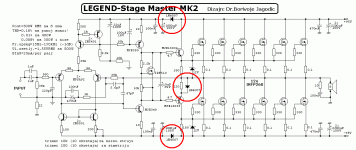
The top and bottom diodes are an attempt to protect the supply rails for the early stages from suffering droops caused by the output stage.
The middle diode probably relates to temperature compensation for the driver bias.
The middle diode probably relates to temperature compensation for the driver bias.
The diodes on the rails are to isolate the rails from the supply when a heavy current is drawn and the output rails will reduce leaving the 1000uF capacitors holding the rails steady. The diode in the emiter of the driver transistor forces it to the centre voltage if anything goes wrong or the drive exceeds the maximum.
The middle diode seems to have two roles: equalize the swing of the lower half of the PP (without it, the negative swing couldn't reach closer than ~2*Vgs from the negative rail), and provide an enhanced class B action to mitigate the effect of the current drive of the lower MOSFets.
Yet another guess... The diodes in the rails would cause a slight time delay at turn-on, so the output stage would be somewhat functional by the time the input stage comes up and immediately tries to correct for any distortions in the waking up output stage. It may reduce the turn-on transient.
The diode in the middle may help overloads be handled more elegantly, by forming a relatively local high negative feedback. A variation of a current limiter.
The diode in the middle may help overloads be handled more elegantly, by forming a relatively local high negative feedback. A variation of a current limiter.
The rail diodes will not add any turn-on delay. They may add a turn-off delay - but I can't decide whether this will be helpful or unhelpful as the input stage will go into saturation as the (now open) feedback loop tries to correct things.
The rail diodes help hold the input stage at operating voltage when or if the output stage suffers severe voltage sag due to a weak PSU not being able to supply the current demanded by the speaker load.
The middle diode may be an attempt to mimic the BJT trick to equalise the load seen by the upper and lower driver transistors.
The upper driver sees the 180r||the load provided by the output stage.
The lower driver sees only the 220r when the diode is not present. Adding the diode may help the lower driver to see a similar load to what the upper driver sees.
I don't know if this BJT trick applies to a mosFET output stage.
- Status
- Not open for further replies.
- Home
- Design & Build
- Construction Tips
- Whats the purpose of these diodes
