As above.
I've reading putting a diode across the relay coils can be beneficial when the power is cut-off.
I'm my case, I'm using a soft start circuit to delay the application of mains AC(1115/230VAC depending on location).
Thanks
I've reading putting a diode across the relay coils can be beneficial when the power is cut-off.
I'm my case, I'm using a soft start circuit to delay the application of mains AC(1115/230VAC depending on location).
Thanks
Traditional mechanical relays normally have a diode to absorb the back emf generated by the coil when the relay is abruptly turned off. Typically, a 1N4004 or similar type of general-purpose diode would cover 99.9% of cases.
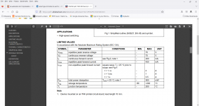
In fact a 1N4148 is sufficient for 99.9% of the cases: it has an Ifsm of 4A, and there are very few relays having a coil requiring >4A:

In fact, using a large, slow diode can be counter-productive: in case of chattering, it can look like a short and blow the control transistor. No such risk with a lean, mean and fast diode like the 1N4148
An important note: a diode should never be used on an AC-controlled contactor. If suppression is required, use a RC snubber or varistor instead
Attachments
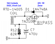
The H9KPXG AC soft start board here on diyAudio, uses a relay to bypass the Inrush Current Limiter disc. This ends the Soft Start phase and enters the Normal Operation mode. The relevant fragment of its schematic is shown below.
H9KPXG's relay has contacts rated for 16 amperes, and the coil requires 5VDC at 81mA to operate. A TN2106 MOSFET switches the coil off and on; when the logic signal named "BYPASS" goes high, the MOSFET turns on, which energizes the relay coil and closes the relay contacts. The contacts short out the Inrush Current Limiter disc, and Soft Start is terminated.
Flyback voltage protection is provided by zener diode D1. It clamps the flyback voltage to +22 volts, which is comfortably less than the maximum drain-to-source voltage of the MOSFET (60V). When a zener diode flyback clamp is chosen, it is connected across the switching transistor (and not across the relay coil).
The little network composed of R12 and C7, reduce coil current after the relay is energized. Since power dissipated in the relay coil is proportional to the square of relay current (P = I * I * R), reduced coil current dramatically reduces coil heating, and increases relay lifetime / reliability. Rod Elliott published this little vignette as Figure 4 of his Project 39 .
_