I am a complete noob to tubes. (that has a nice ring to it doesn't it? Tube noob) I was just gifted a pair of Dynakit MKIII's. They have a full set of low hour chinese KT88's in them. Otherwise they are totally stock. One channel won't bias up high enough (runs out at about .96 volts with a target of 1.56) I have found a bias repair kit for about $5 per channel which should get me going again. Likely a good place to start, but I am up for a project. I know of several board upgrade options, but I am looking for opinions and guidance on money best spent to make these things sing.😀
"One channel won't bias up high enough "
Go ahead and rebuild the bias supply, but I would guess that the reason the amp won't bias properly is the tube NOT the bias supply.
Go ahead and rebuild the bias supply, but I would guess that the reason the amp won't bias properly is the tube NOT the bias supply.
A bad bias supply will cause way too high a reading on the biasset pin, not too little. Too little is a weak rectifier, or a weak output tube (or pair)
I don't know if they have gotten better, but I watched fire shoot out of a friend's Citation II in the 1990's due to a chinese KT88 failure. I do not use chinese power tubes as a result.
Sheldon
I don't know if they have gotten better, but I watched fire shoot out of a friend's Citation II in the 1990's due to a chinese KT88 failure. I do not use chinese power tubes as a result.
Sheldon
"Bias Repair Set for Mark 3Replaces selenium bias rectifier with silicon diode, also includes resistors & capacitors used in bias circuit that are not on the printed circuit board. Parts Included: 1K 2W Resistor, 18K 2W Resistor, .022uF 630V Capacitor, 100uF 100V Capacitors x 2pcs, & 1N4007 Diode. Some of these parts are also included in the Dual Bias Kit on this page.One set required per amplifier"
Looks like this should fix the bias issue. I swapped all the tubes from the good channel to the "bad" and it didn't fix the issue, so I was leaning towards a rebuild, but this little bias repair set seems like a no brainer. But from there....
Looks like this should fix the bias issue. I swapped all the tubes from the good channel to the "bad" and it didn't fix the issue, so I was leaning towards a rebuild, but this little bias repair set seems like a no brainer. But from there....
I had a pair of MkIIIs at one time and they sounded decent. I rebuilt them with better resistors and caps, and added a fan. No doubt you're better off without the selenium rectifier. I can't comment on the Chinese tubes; I had mine back when you could buy new brand name KT88s for $20 a matched pair or thereabouts. I'd at least check the main filter cap sections. Keep 'em or sell 'em? Depends on your commitment to tubes. I found they heated up the room too much and had high operating costs to keep them running at their best. The bass was always a bit muddy at best.
The bias supply should be rebuilt as a matter of course if it is still stock with a selenium rectifier - that means it is very old.
The voltage you read on the "bias" test pin is actually the cathode current. It is the voltage across the cathode resistors. CHECK THEM. They are often bad.
When the current is higher the voltage red is higher.
The VALUE of the cathode resistor was selected at a time when VOMs or VTVMs were standard, not DVMs, so it was hard to reliably read voltages much below 1 volt - at least for most kit builders.
You can improve the bass by reducing the cathode resistor value by a factor of 10 or more - but it is a good idea to put a sticker on the chassis to make sure that you don't forget the change and a future buyer has a shot at not killing his/herself trying to bias the amp! 😀
The wattage of the cathode resistors was selected to act as a bit of a fuse in the event of a tube short - not a bad idea since the outputs can and do short, although not very often... it keeps the amp from frying...
So, check and change the cathode resistors... especially if after you fix the bias supply (you can check it now, it ought to be around minus 70-90vdc (iirc) on the high side of the bias adjust pot) it still doesn't appear to bias properly.
It's a good amp to get ur feet wet on - but keep your hands out of it when it is on, you can get a nasty shock or worse. Be very careful when testing voltages, especially on the bottom. NEVER hold the chassis with one hand when testing with the other.
_-_-bear
Oh, Iirc, the Mk II wanted 6550/Kt88 while the MkIII wants 6CA7/EL34 - they won't make full power without the proper tube with proper plate impedance, but they will work ok...
_-_-bear
Oh, Iirc, the Mk II wanted 6550/Kt88 while the MkIII wants 6CA7/EL34 - they won't make full power without the proper tube with proper plate impedance, but they will work ok...
The Mk.ii and Mk.iii had what was effectively the same OPT. U-L tapping slightly different is about the size of it, and it was the ii that came with EL34's.
cheers,
Douglas
I don't know if they have gotten better, but I watched fire shoot out of a friend's Citation II in the 1990's due to a chinese KT88 failure. I do not use chinese power tubes as a result.
The 90's vintage Chinese KT88's will remind you that the Chinese invented fireworks! I got a "deal" of 50 of them in the mid 90's. They look well built, but some will red plate at under 30 watts. They will also self destruct without warning. I made guitar amps with them, running them very conservatively at 370 volts in a 35 watt amp. Over half of those tubes failed in the first few months, and one even shattered while playing. Most failed spectacularly with heavy fireworks inside the tube. I still have about 20 of them stashed somewhere. I switched to Sovteks and there were no more fireworks.
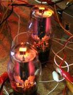
The recent vintage Chinese power tubes seem to hold up pretty well. I haven't had any self destruct despite my total ignorance of the maximum ratings. The photo of the Chinese 6L6GC was taken a few years ago. Those tubes had already served a tour of duty in a Fender Bandmaster. I have since used them for several "experiments" where the lives of the tubes are at risk. They are still alive today!
Attachments
Bear got the numbers reversed. The KT88 goes with the III.
The loads a-a are otherwise the same though.
In any case, I have had quite my fill of loop FB amps. My Mk.iii( also gifts ), are now running a LTP of type 6AC7, E-linear rigged and I doubt very much I'll ever take that circuit out of service.
The note on cathode R value for fixed bias current measurement got quite a giggle out of me. These were my first tube amps and I used 1R resistors as current sensors. Everything else after that got 10R and indeed I managed to forget. What issues I had( and inflicted upon those poor rectifier tubes ) trying to bias them until I figured it out.
cheers,
Douglas
Everything else that Bear advised was A OK. I had Dyna mark3's for about 10 years, myself. Now, I have Mark 4's.
I rebuilt a pair with SDS boards from Triode Electronics, Poseidon input boards, RCA 12BH7s, Raytheon 5751s, MIT RTX couplers, a new bias supply and SED 6550s. It turned out to be quite the slammin' amplifier and I preferred them over my ol' rebuilt Dynaco 70.
The end result was not a spongey tubey sound in the classic vintage sense.
The end result was not a spongey tubey sound in the classic vintage sense.
That's whatcha get for standin' on yer head too much! 😛
maybe so...but it can be quite comfortable...🙂
cheers,
Douglas
I was just gifted a pair of Dynakit MKIII's... Otherwise they are totally stock.
A few summers ago I bought a set of Mark III in a condition very similar to yours. Going into it, I knew I would be spending more than a couple of dollars to fully rebuild them. Here's a couple of absolutely critical areas which must have your attention:
- Can capacitor
- Bias supply capacitors
- Coupling capacitors
- Bias supply selenium rectifier
- Bias adjustment pot
I'd also suggest you consider adding small (50~200 ohm) flameproof resistors at the screens of the output tubes. This seems to help the expensive KT88 last much longer. To make the rectifier tube last longer, you might want to put UF4007 diodes at the rectifier socket. They go in series between the power transformer HV secondary and the rectifier's anodes. You can use the empty pins on the socket as tie points. Also check your line voltage, and if it's much over 117VAC think about building a small bucking autoformer to bring it down into spec.
While I had mine apart I replaced all the sockets, switches, cords and connectors with new. I put in new stainless steel hardware to replace the rusty old screws. In hindsight, I probably should have repainted the transformer endbells and had the chassis re-plated, but oh well. By this point the project budget was already well over $500~600 (includes new tubes) and I wasn't in the mood to spend any more. I will say that I am very happy with the end result, and I fully expect the amps to outlive me.
I've taken a number of photos before, during and after the rebuild process. Feel free to browse through them and ask questions if you like.
Mark III pictures by Ty_Bower - Photobucket
hey-Hey!!!,
Build in two bias pots. They will present no change to the final's grid circuit load and the benefit is obvious. Get small ones so that they can be mounted at the end of the slot next to the original bias pot mount. It may take a bit of work with a grinder but it is a small mod.
cheers,
Douglas
Build in two bias pots. They will present no change to the final's grid circuit load and the benefit is obvious. Get small ones so that they can be mounted at the end of the slot next to the original bias pot mount. It may take a bit of work with a grinder but it is a small mod.
cheers,
Douglas
After this discussion, I am thinking that maybe I should fix the bias on both amps and give them a good cleaning and send them on their way. Doing a rebuild and cap replacement can cost up $300 depending on how it is done. That is without looking at tubes at all. Thanks for all the feedback and advice. Of course that decision is libel to change as soon as I live with a healthy set of amps for a while. This audio thing... it really is a disease. Even worse when you feel the need to take apart what is already working to try and make it better🙂
Hey DaveM
The following is relevant only if you haven't already tried a triode amp, but would like to... Otherwise feel free to ignore this...
If you get your Mark III's working, you might try triode wiring them and giving them a listen, before you move on. A before-and-after comparison should be interesting. A lot of people discovered triode power amplifiers this way, usually with a Dyna Stereo 70, but a pair of Mark III's will do every bit as well. It's a simple mod too.
Disconnect the Ultralinear taps from the tube sockets (6550A pin 4, green and green/white wires from the output transformer). Cover and fully insulate the wire ends with heatshrink tubing. Make it so they can't possibly short anything out. Roll up the wires and tuck them away from harm.
Install a 220 ohm 1W resistor from 6550A pin 4 (screen grid) to pin 3 (anode).
That's it.
It won't be a properly designed triode amp (feedback loop resistor and cap values would need adjustment), but a quick listen should tell you if you prefer the sound of triode output power amps. A friend and I did this way back in the late 1980s, fully expecting to hear increased distortion and weak bass. Instead, we heard details and an effortless sound we never knew we were missing. I've been a low-power/triode guy ever since. I can't guarantee you'll feel the same way, but heck, you'll be working on the amps anyway so why not have a go at triode?
You'll probably want to return them to stock before you sell them. Easily done.
--
bottom line is that if you want tube amps, unless you scrounge and build ur own you can't get anything cheaper than you have now... the cost of redoing the amps is pretty low unless you go to supplier who charge a premium for premade "kits" and step by step instructions... there is really no need for that.
You can run it with what is there now, assuming you get the various voltages where they need to be and there are no bad coupling caps or off value resistors and the tubes work.
Besides a working amp brings more than a broken one.
_-_-bear
You can run it with what is there now, assuming you get the various voltages where they need to be and there are no bad coupling caps or off value resistors and the tubes work.
Besides a working amp brings more than a broken one.
_-_-bear
- Status
- Not open for further replies.
- Home
- Amplifiers
- Tubes / Valves
- What should I do with my Dynaco MKIII's