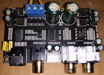
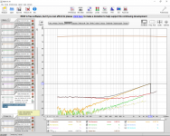
What Is Wrong With This DAC? There is significant distortion and it measures far worse than the LJM CS4398.
Attached Picture: Measurements of CIRMECH CS4398 DAC With NJM4580D.
Does anyone else have this DAC? Has anyone else measured it? FYI: I remeasured my ES9028Q2M to make sure I did not have a problem with my ADC.
Attached Picture: Measurements of CIRMECH CS4398 DAC With NJM4580D.
Does anyone else have this DAC? Has anyone else measured it? FYI: I remeasured my ES9028Q2M to make sure I did not have a problem with my ADC.
Attachments

Last edited:
There are probably all kinds of things wrong with it. Power supply problems, decoupling problems, SPDIF jitter problems, layout problems, insufficient quality ground plane problems, etc.
If you want to figure out more about what is causing the measurements to be as they are, you should probably start by tracing out a schematic of the PCB. That should be very easy to do if it is on a 2-layer PCB.
Then download and study datasheets for the components used. Are the components configured and applied as recommended in the datasheets?
Take a look at the PCB layout. What is the grounding scheme? Is it good enough to RF and low distortion audio right next to each other on the board?
Measure all the voltages and scope out the AC signals looking for problems.
If after all that you don't find a good explanation, then maybe consider the quality of the passive components and voltage regulators. If selected by the designer for lowest possible BOM cost, you may need to replace some parts and then remeasure.
There are more things you could look at, but probably you will find an explanation pretty quickly. If not, post about what you have tried so far and I'm sure some people will be happy to help you figure it out.
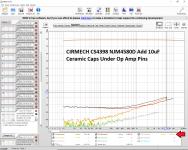
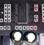
So far I was able to achieve an approximate 10 dB improvement in the harmonic distortion by adding two 10uF monolithic ceramic capacitors directly under the op-amp and soldered to the socket pins. I also bridged the ground plane which was split under the op-amp due to poor layout/routing. It only has 2 layers but the layout could have been much better.
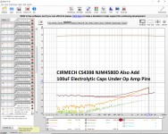
Adding two 100uF electrolytics (next step) improved the second harmonic but no change to the huge 3rd harmonic.
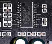
I assume the rest of the problem is related to the terrible bypass capacitor placement, layout and grounding for the CS4398 especially the analog Vcc and related pins on that side of the CS4398.
I am not sure it is worth the effort trying to use copper tape or copper braid and additional capacitors to fix the analog bypassing around the CS4398. It looks like this is a terrible design. I liked the LJM CS4398 and thought this board would make a nice easy way to add coax and optical input to my project amplifiers.
Maybe I should stick with the ES9028Q2M board I bought or maybe I should try the ES9038Q2M to see if it is better. Is the ES9038Q2M actually better than the ES9028Q2M?
Adding two 100uF electrolytics (next step) improved the second harmonic but no change to the huge 3rd harmonic.
I assume the rest of the problem is related to the terrible bypass capacitor placement, layout and grounding for the CS4398 especially the analog Vcc and related pins on that side of the CS4398.
I am not sure it is worth the effort trying to use copper tape or copper braid and additional capacitors to fix the analog bypassing around the CS4398. It looks like this is a terrible design. I liked the LJM CS4398 and thought this board would make a nice easy way to add coax and optical input to my project amplifiers.
Maybe I should stick with the ES9028Q2M board I bought or maybe I should try the ES9038Q2M to see if it is better. Is the ES9038Q2M actually better than the ES9028Q2M?
Attachments
-
 CIRMECH CS4398 NJM4580D.png207.6 KB · Views: 141
 -
 CIRMECH CS4398 NJM4580D Add 10uF Ceramic Caps Under Op Amp Pins.png233.8 KB · Views: 137
 -
 CIRMECH CS4398 NJM4580D Also Add 100uF Electrolytic Caps Under Op Amp Pins.png232.5 KB · Views: 142
 -
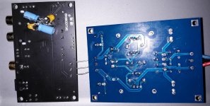 20201216_172630.jpg867.8 KB · Views: 116
 -
 CIRMECH CS4398 Terrible Layout Design.jpg248.5 KB · Views: 115
 -
 CIRMECH CS4398 Terrible Layout Design 2.jpg328.8 KB · Views: 127