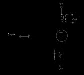
Is this the simplest you can get with a tube amp? From what I understand the basics of an amp go like this:
1) Signal goes through a coupling capacitor to eleminate DC
2) Signal goes to tube grid and modulates DC current from plate to collector
3) modulated DC goes through a output transformer
4) profit?
1) Signal goes through a coupling capacitor to eleminate DC
2) Signal goes to tube grid and modulates DC current from plate to collector
3) modulated DC goes through a output transformer
4) profit?
Attachments
cuallito said:Is this the simplest you can get with a tube amp?
With no DC from the source you could lose the input coupling cap, and the cathode bypass may not be necessary... you do need a grid leak resistor thou (and a power supply)
dave
thanks dave, the only reason I put the cathode bypass in there is I always see it in other designs. What's it for anyway?
wow thanks guys. im learning a lot! Is a grid leak resistor simply a resistor infront of the grid? So I could basically simplify it down to this?
Also, what are the advantages of using more complicated designs versus ultra-minimal ones like this one? And do I need a resistor between the collector and outpot transformer?
Also, what are the advantages of using more complicated designs versus ultra-minimal ones like this one? And do I need a resistor between the collector and outpot transformer?
Attachments
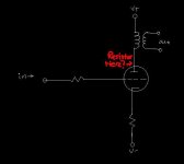
The grid leak is a high-value (50K->10meg) resistor that goes from the grid to ground (or other reference point). Its purpose is to hold the grid at ground on a DC basis. The size is chosen to be as large as possible, consistent with the expected grid leakage current of the tube.
That would be a grid stopper. A grid leak goes from the grid to ground. No, you don't need a resistor between the plate and the transformer, but you could replace the transformer with a resistor.
Here's a good article that should answer many of your questions:
http://www.tubecad.com/articles_2003/Grounded_Cathode_Amplifier/index.html
Here's a good article that should answer many of your questions:
http://www.tubecad.com/articles_2003/Grounded_Cathode_Amplifier/index.html
SY:
What would be the effect of putting a battery under the cathode (assuming there's a CCS up on top for setting the current, and the battery's voltage is equal to the required bias voltage)? Would that be equivalent to a cathode resistor bypassed with a (near) infinitely large capacitor? In other words, maximum possible gain, lowest possible output impedance, and highest possible distortion?
The bypass increases gain and lowers source Z, at the expense of increasing distortion.
What would be the effect of putting a battery under the cathode (assuming there's a CCS up on top for setting the current, and the battery's voltage is equal to the required bias voltage)? Would that be equivalent to a cathode resistor bypassed with a (near) infinitely large capacitor? In other words, maximum possible gain, lowest possible output impedance, and highest possible distortion?
Yeah, it would be pretty close. The differences would be around the fringes: the battery will have a higher source Z than the cap-bypass at high frequencies and a lower source Z at very low frequencies. But basically, the same.
Thanks. So it's still the same tradeoff between output Z and distortion, and picking which is more important for the application.
Cuallito,
You're welcome.
Cuallito,
You're welcome.
Yes, although as a practical matter, at midband there won't be much difference between the battery and the cap.
It seems like you're trying to do things the hard way. 3000V? High turns ratio? Squirrelly O/P tube? What's the point?
20-40WRms from a single stage amp? Btw, how is the 6HV5 'squirrely'? Its specs look interesting, at any rate.
Well if that's all you want, use a pair or two of 6550s.
Ask anyone who used one of the old Acoustat amps. Random shorts, open, and oscillations.
Btw, how is the 6HV5 'squirrely'? Its specs look interesting, at any rate.
Ask anyone who used one of the old Acoustat amps. Random shorts, open, and oscillations.
thoriated said:Anybody think an amp like this has any redeeming value?🙂
lose the caps (they are some sort of feedback?), use triode strapped EL84s, maybe change the cathode R to a constant current source, adjust the other values -- including the very dangerous B+ --and it would be very simple and quite interesting.... anyone have an idea on the 1:10 phase splitter, step-up interstage?
dave
lose the caps (they are some sort of feedback?), use triode strapped EL84s, maybe change the cathode R to a constant current source, adjust the other values -- including the very dangerous B+ --and it would be very simple and quite interesting.... anyone have an idea on the 1:10 phase splitter, step-up interstage?
ah! like what i have done here.
http://diyparadise.com/simpleel84.html
http://diyparadise.com/buildel84.html
http://diyparadise.com/buildel84b.html
http://diyparadise.com/buildel84c.html
a cheap and excellent 1:3 interstage is the one sold by antique electronic supply.
http://diyparadise.com/pt156.html
if you load the secondary properly, this cheap interstage works pretty well.
donjuan
Hi, Donjuan -
The P-T156 should work, or the P-T124E for a little more open circuit inductance. You could even use two with the primaries in parallel for more step up. More manufacturers used to make transformers like this. The 1Khz square wave tops and bottoms don't look bad at all, indicating decent low end extension.
Jensen or Lundahl should have some wide band candidates for this type of application also, but at a higher cost. Maybe a custom Sowter🙂
Hi, Planet10 -
The 1.5 pf caps were my idea of neutralizing most of the Miller capacitance of the output tubes so that the capacitive loading wouldn't be too horrendous at the input. If pentodes as pentodes were used for the single stage amp, the caps could probably be dispensed with, but I was thinking a cathode winding for each half would then be needed to provide local feedback and improve the damping while stabilizing the gain.
I wonder if an off the shelf output transformer could be rigged in this way so that the 0-4-16 ohm taps could double as both the output winding and the cathode connections. Just a thought.
Ask anyone who used one of the old Acoustat amps. Random shorts, open, and oscillations.
I feel myself losing interest in the 6HV5🙂
- Status
- Not open for further replies.
- Home
- Amplifiers
- Tubes / Valves
- what is the simplest possible triode amp?