The 2200pF was added for aesthetic and decorative purposes, but then that made the inclusion of the 68pF's necessary to recover stability.
can we use the miller capacitors in general configurations? any drawbacks... I all have styroflex caps in those values in 63v AC. Does it improve sound quality in any sense.
I use to see the styroflex caps in old marantz amps seems it might be for miller since such low values dont make sense in psu decoupling.
can i use that in 5200/1943 pair?
but overall does it improve any sound quality?
I use to see the styroflex caps in old marantz amps seems it might be for miller since such low values dont make sense in psu decoupling.
can i use that in 5200/1943 pair?
but overall does it improve any sound quality?
The 2200pF was added for aesthetic and decorative purposes, but then that made the inclusion of the 68pF's necessary to recover stability.
So it shouldnt have been added but since it was added
then other caps were to be added.....
Can we conclude that all theses caps can be removed.?...😉
The 2200pF was added for aesthetic and decorative purposes, but then that made the inclusion of the 68pF's necessary to recover stability.
😀
So it shouldnt have been added but since it was added
then other caps were to be added.....
Can we conclude that all theses caps can be removed.?...
It's a very practical thing to limit bandwith of consumer audio amplifiers. 160 kHz is considered adequate bandwith for "mid fi" gear and in fact there is very little to be gained by extending it. As an audio tweaker, feel free to build a faster circuit and it's OK as long as it's stable in your application.
There's more than one way to address stability in high speed global feedback circuits. Read up on Walt Jung's feedforward compensation. It effectively decreases loop gain at higher frequencies by opening up the feedback loop at higher frequencies while simultaneously reducing loop gain with a zobel snubber on the output. It's tricky (and doesn't always work the way you'd like) but modest increases in speed and reductions in distortion (by virtue of more global feedback /higher loop gain) can sometimes be realized without the usual instability issues of high speed, high loop gain amplifiers.
Last edited:
Here is what I mean:So it shouldnt have been added but since it was added
then other caps were to be added.....
Can we conclude that all theses caps can be removed.?...😉
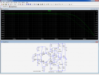
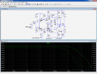
First, a sim without any explicit compensation: nice and regular amplitude & phase response, roll-off begins at ~250KHz.
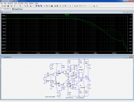
Second, the 2n2 is added: this predictably creates ugly quirks
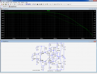
Third, all the capacitors in place: the nasty quirk is swept under the carpet, and the roll-off starts at 35KHz.
Demolition job is completed.
If one wishes more roll-off, the good solution is to increase the time constant of the passive input filter, not to mess-up with the loop parameters
Attachments
Last edited:
If you check out this by simulation (frequency response - top roll-off character between 1 and 10 MHz) you will see, that this will be heavily dependent from the used transistor types resp. it's Ft.So it shouldnt have been added but since it was added
then other caps were to be added.....
Can we conclude that all theses caps can be removed.?...😉
Additional this will be heavily dependent from the kind of PCB layout (guidance of conductor traces on PCB) - unfortunately this isn't easy to take into account while performing a simulation, because you must introduce all unwanted parasitic elements (e. g. the parasitic capacity part of the 2200 pF).
This means, that a measurement of the frequency response in the aera between 100 KHz and 10 or 20 MHz is absolutely necessary for investigating the behaviour in this aera in real live - and not only by simulation (unfortunately I haven't therefore the necessary setup).
When there are one or more peaks before the falling edge, the risk is very high to get unwanted oscillations.
Here is what I mean:
First, a sim without any explicit compensation: nice and regular amplitude & phase response, roll-off begins at ~250KHz.
Second, the 2n2 is added: this predictably creates ugly quirks
Third, all the capacitors in place: the nasty quirk is swept under the carpet, and the roll-off starts at 35KHz.
Demolition job is completed.
If one wishes more roll-off, the good solution is to increase the time constant of the passive input filter, not to mess-up with the loop parameters
Good work in first round. The ugly quirks will be create through the unity gain character in the upper frequency range (2n2 means a short wire between output and inverted input from a certain frequency).
Second round must be the investigation of this in real live under real conditions.
I guess, no compensation capacitor is necessary (independend of the transistor Ft's), if one replace the Sziklai darlington in the output through a normal darlington, because then only one voltage gain stage is in the global NFB loop (currently there are two voltage gain stages).
Last edited:
What happened to basic stability issues? First sim show 220 degrees of phase shift at unity (0db) gain frequency. (around 12 mhz) Second is 135 degrees at around 3 mhz. third is 150 degrees around 7 mhz. 2n2 cap is lead compensation, and if done right does work. If sims are right, first amp is an oscillator, I would think.... Also why the big deal about ugly quirks below unity gain frequency and way outside the audio band....My 2 cents.
You cannot draw useful information about loop phase issues from the In-Out phaseshift.What happened to basic stability issues? First sim show 220 degrees of phase shift at unity (0db) gain frequency. (around 12 mhz) Second is 135 degrees at around 3 mhz. third is 150 degrees around 7 mhz. 2n2 cap is lead compensation, and if done right does work. If sims are right, first amp is an oscillator, I would think.... Also why the big deal about ugly quirks below unity gain frequency and way outside the audio band....My 2 cents.
The loop gain has to be measured properly.
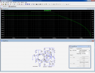
With no capacitors at all, the phase margin is 93°, which is excellent.
With the 2n2, this is reduced to less than 36°; this is becoming marginal.
With all the caps in place, the margin rises to 133°, which is very good but not particularly useful, and this comes at a cost: the loop gain begins to roll off as early as 15KHz, the phase is not linear, and the slew rate is most probably damaged too.
Attachments


Thank you for your explanations. My circuit theory stuff is 30 years old and mostly unused (and pre spice) so be patient with me. My only other quibble is that lead compensation is normally added in after miller and other compensations (tweak after feedback has been put in), so (to me) it is somewhat misleading to analyze the circuit with just the 2n2 cap, but would be more correct to have just the 68 pf caps, and then see what corrections the 2n2 cap. (i.e. the 2n2 cap is useless until the other caps are in place).
Capacitors cost nothing. I would begin by first building the circuit as specified, and check everything is OK. It should: the circuit is safe as a Volvo, and almost as boring.so altogether its better to remove those caps? as its degrading most of the parameters..
Then, when you're satisfied with it, try removing the capacitors (all at a time: removing them partly could lead to problems).
If you don't detect problems, you can compare the two versions and choose what you like best.
Little could go wrong, the loop gain is so small that even with extreme transistor types it will remain stable, unless your wiring/layout is really hairy or you opt for multiGHz types.
Note that there are probably even better solutions than removing the caps completely: a small measure of lead compensation could certainly bring further improvements without even requiring additional comp caps.
For instance, replacing the 2n2 by a 470p in series with 47R would bring the benefit of phase advance without too many inconvenients.
But this has to be taylored to the exact type of transistor you use.
Simply removing the caps requires no discrimination to be effective.
That's right, but here with such a small loop gain the first thing to do is to check if and how much Miller compensation has to be added, and then add some lead as a finishing.Thank you for your explanations. My circuit theory stuff is 30 years old and mostly unused (and pre spice) so be patient with me. My only other quibble is that lead compensation is normally added in after miller and other compensations (tweak after feedback has been put in), so (to me) it is somewhat misleading to analyze the circuit with just the 2n2 cap, but would be more correct to have just the 68 pf caps, and then see what corrections the 2n2 cap. (i.e. the 2n2 cap is useless until the other caps are in place).
But here, that lead comp is so oversized that it looks like a statement: the expression of an article of faith, an extremism of some kind: there is no way one could arrive at such a value in a normal design process: it has been decided upfront, and then the rest has been made to fit (more or less).
This results in something seriously suboptimal, but the small loop gain is forgiving enough to allow for such oddities.
With a lead cap one tenth of the original value and a 100R series resistor, the margin is practically unchanged, but the overall perfs are much improved with the transistors used for the sim.
Here, we begin to be very device specific, and in reality there could be serious variations depending on the actual transistors used, unlike the complete removal of the caps which should be rather device tolerant.
However, if we look at the group delay flatness, the absence of caps remains the best option: up to 200KHz it remains totally flat.
Attachments

Gave it in #10what about the stability point? when the caps are removed...
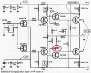
I have build this version, And when I plug in the power supply, there's no current flowing through the power transistor. ( Voltage on 0.33R nearly 0V) I thought this layout was running in Class B. But when I remove the 68pf cap at below of schematic, the circuit is working normal in Class A (voltage at 0.33R is ~0.45V)
Is every one tell me why? Was 2SC1096 died?
Thanks.
Is every one tell me why? Was 2SC1096 died?
Thanks.
Attachments
- Status
- Not open for further replies.
- Home
- Amplifiers
- Solid State
- what is the role of the 68pf and 2200pf cap in Hiraga Super class A 30W