Thank you for your reply. Do you mean it is a damping resistor?Like in tube circuits, except it is more necessary in a wider bandwidth circuit.
But most constant current source circuits do not seem to have this resistance, so I am a little confused about its function
I'm sorry my English is poor, and I don't quite understand what [base stopper] meansYes - rayma has got it - a base stopper
A base stopper resistor is a series base resistor used to reduce or prevent ringing and/or oscillation.
The term is a colloquialism. You can call it a damping resistor in that it could reduce the Q of the ringing.
The need for such a resistor depends on the parts, construction, and circuit in which the current source is used.
You could breadboard the current source, and see how the base resistor's presence and value affects the output.
Last edited:
Thank you for your reply.A base stopper resistor is a series base resistor used to reduce or prevent ringing and/or oscillation.
The term is a colloquialism. You can call it a damping resistor in that it could reduce the Q of the ringing.
The need for such a resistor depends on the parts, construction, and circuit in which the current source is used.
You could breadboard the current source, and see how the base resistor's presence and value affects the output.
I built a circuit with a bread board for testing

Good, post some results here for discussion.
The resistor lead to the transistor base should be short and direct.
The resistor lead to the transistor base should be short and direct.
In low-frequency circuit, R4 is not necessary, right?Good, post some results here for discussion.
The resistor lead to the transistor base should be short and direct.
If the transistors have wide bandwidths, which they will, this is not a low frequency circuit.
A circuit can oscillate at say 100 MHz without an input at that frequency, or even any input at all.
A circuit can oscillate at say 100 MHz without an input at that frequency, or even any input at all.
Thank you very much.If the transistors have wide bandwidths, which they will, this is not a low frequency circuit.
A circuit can oscillate at say 100 MHz without an input at that frequency, or even any input at all.
It plays a stabilizing role in the circuit
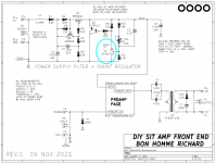
Q1 and Q2 are connected in a negative feedback loop, which like all NFB loops, might possibly oscillate. Resistor R4 works with the collector-to-base capacitance of Q1 to provide dominant pole (Miller) compensation, which stabilizes the loop and prevents oscillation. Often the feedback loop is perfectly stable even without R4, depending on device choices and bias levels. But designers include R4 anyway, as an inexpensive belt-and-suspenders safety measure.
Very good explanation, thank you!Q1 and Q2 are connected in a negative feedback loop, which like all NFB loops, might possibly oscillate. Resistor R4 works with the collector-to-base capacitance of Q1 to provide dominant pole (Miller) compensation, which stabilizes the loop and prevents oscillation. Often the feedback loop is perfectly stable even without R4, depending on device choices and bias levels. But designers include R4 anyway, as an inexpensive belt-and-suspenders safety measure.
Follow-up question if the OP permits,
Does it also serve its purpose if it contributes to adjusting output dc offset?
At times when I couldn't make the dc offset set to an almost zero dc, I attached a small resistor at their bases.
Does it also serve its purpose if it contributes to adjusting output dc offset?
At times when I couldn't make the dc offset set to an almost zero dc, I attached a small resistor at their bases.
Base current is not highly thermally stable, so not an ideal method.
Do you mean the bases of output power transistors? Higher values than necessary may also cause more distortion.
Do you mean the bases of output power transistors? Higher values than necessary may also cause more distortion.
Is that resistor necessary in the Precision Constant-Current Sink example of the TI datasheet of TL431? See p.29, Fig. 10-15 here:
https://www.ti.com/lit/ds/symlink/tl431.pdf
https://www.ti.com/lit/ds/symlink/tl431.pdf
Check out the pin compatible, vastly more stable, version made by Diodes Inc: the AS-431 . I used it in the Bon Homme Richard front end card for VFET/Theseus and had no problems at all. I like to believe the AS in the part number means Augmented Stability.
_
_
Attachments
- Home
- Amplifiers
- Solid State
- What is the role of R4 in the constant current source circuit