I've seen on these pages a square wave reproduction from a phono stage (was it on Salas's "Simplistic" thread?).
So I'm wondering what constitutes a "good" square wave response from an RIAA circuit ... how do you tell it is "good" rather than "bad"?
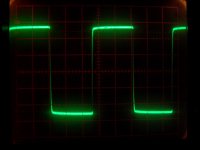
Here is the square wave response from my own phono stage (whose circuit originally came out of the "Le Pacific" schematic, dating from the '80s ... but which has diverged quite considerably from that 🙂 ). EDITS:
#1 - frequency was 1KHz.
#2 - there is a Hagtech RRIAA between the sig gen and the phono stage.
Each graticule is 50mV; the 2 flat lines are approx. 210mV apart and each "overshoot" is approx. 15mV.
Thanls,
Andy
So I'm wondering what constitutes a "good" square wave response from an RIAA circuit ... how do you tell it is "good" rather than "bad"?
Here is the square wave response from my own phono stage (whose circuit originally came out of the "Le Pacific" schematic, dating from the '80s ... but which has diverged quite considerably from that 🙂 ). EDITS:
#1 - frequency was 1KHz.
#2 - there is a Hagtech RRIAA between the sig gen and the phono stage.
Each graticule is 50mV; the 2 flat lines are approx. 210mV apart and each "overshoot" is approx. 15mV.
Thanls,
Andy
Attachments
Last edited:
At what frequency was this taken? 1kHz?
Yes, 1KHz. I will edit my original post to put that in.
Andy
Hi,
Square in and your looking at out at 1KHz ?
Should not look like that.
Good is a square wave into a very accurate
inverse RIAA filter into RIAA and looking at
the output, but it still won't tell you much.
Square wave output is intrinsically defined
by the frequency response, which is easier
to measure than infer from square waves.
rgds, sreten.
You've got a rise in the treble- a little trim will take care of that.
Thanks, SY. Can you tell me how the graph shows you that I have a rise in my treble response? 😕
Is it the fact that the 'flat' lines are very slightly tilted downwards to the R?
Or does the treble rise cause the initial peak?
The HF RIAA response I have measured (feeding my sig gen through a Hagtech passive reverse RIAA) is as follows - L channel, relative to 1KHz:
* 8KHz 0.04dB
* 10KHz 0dB
* 15KHz 0dB
* 20KHz -0.22dB
* 50KHz -1.46dB
The R channel is similar but not identical.
Thanks,
Andy
Thanks,
Andy
Last edited:
I see some tilt which indicates low frequency rolloff.
Do you mean the fact that the 'flat' lines are very slightly tilted downwards to the R, indicates low frequency rolloff, Frank?
The LF RIAA response I have measured (feeding my sig gen through a Hagtech passive reverse RIAA) is as follows - L channel, relative to 1KHz:
* 80Hz -0.18dB
* 60Hz -0.18dB
* 50Hz -0.22dB
* 40Hz -0.35dB
* 30Hz -0.35dB
* 20Hz -0.35dB
The R channel is similar but not identical.
Thanks,
Andy
Hi,
Square in and your looking at out at 1KHz ?
Should not look like that.
Good is a square wave into a very accurate
inverse RIAA filter into RIAA and looking at
the output, but it still won't tell you much.
Square wave output is intrinsically defined
by the frequency response, which is easier
to measure than infer from square waves.
rgds, sreten.
Thanks, sreten.
Yes, 1KHz square wave in - but via a Hagtech reverse RIAA module. The pic shows the output from the phono stage.
I deduce from your final 2 paragraphs that looking at a square wave actually doesn't give you much useful information about the accuracy of the RIAA response?
Thanks,
Andy
Both. A low cut and a high boost are the same thing, really. Downward tilt of the top means the lows need boosting (or the highs reducing). The sharper any peak in the frequency response in the treble, the more pronounced the overshoot after the voltage rise- if the frequency response peak is sharp enough, you'll see ringing as well following the rise. In this case, there's a damped overshoot, so a bit of network trimming should bring things right in.
Looks like a rise in the HF response to me as well.
I built the Hagtech inverse RIAA network from the schematic on the website; I used the 6.2n capacitor value on the schematic, not the two 3.3n capacitors in parallel. It measured -0.7dB at 20kHz versus the ideal response, and LTspice simulation showed that as well.
Does your circuit employ the so-called "Neumann pole"? That might explain the response you are seeing.
Here is the response I got from a pretty standard series feedback 5534 op amp phono stage I built at 1kHz, 200mV/div:
If anything, I have a slight loss at HF according to this.
-Erich
Attachments
Does your circuit employ the so-called "Neumann pole"? That might explain the response you are seeing.
-Erich
Good thinking, Erich! 🙂 Yes, I have employed the "Allen Wright" 50KHz pole.
Do I understand you correctly:
* if I had not used the Neumann resistor in the passive feedback circuit, I wouldn't see that peak on the leading edge of the square wave (assuming my RIAA response follows the theory)?
* so, given that I do want to use the Neumann pole ... in fact the square wave response that I got is "normal"?
Thanks,
Andy
Ideally you would get a perfect square wave with exact RIAA/inverse RIAA response. Of course things are not so ideal, since the HF response of the inverse RIAA network can't keep rising indefinitely, therefore the -0.7dB response I measured and simulated, also the frequency response of the phono stage is likely limited at both LF and HF. Since your circuit has the additional pole that causes a rising HF response, your square wave response is to be expected. I haven't tested any circuits with the 50kHz pole, so I don't know the exact waveshape. At least your results don't indicate excessive LF rolloff or unwanted phase shifts, just the expected HF rise. So I think you got the results I would have expected; everything normal with the exception of the added 50kHz pole.
Hi,
Well you can't infer anything about the phono stage beyond
the accuracy of the inverse RIAA, from the square waves.
Either way you need to measure the response accurately
for one or the other to infer any accuracy of the other.
e.g. a bit of overshoot could be be due to one being right,
the other wrong, both being being wrong, both being a
little wrong - both causing overshoot, or both being more
wrong, one undershooting the the other more overshooting.
rgds, sreten.
Last edited:
Ideally you would get a perfect square wave with exact RIAA/inverse RIAA response. Of course things are not so ideal, since the HF response of the inverse RIAA network can't keep rising indefinitely, therefore the -0.7dB response I measured and simulated, also the frequency response of the phono stage is likely limited at both LF and HF. Since your circuit has the additional pole that causes a rising HF response, your square wave response is to be expected. I haven't tested any circuits with the 50kHz pole, so I don't know the exact waveshape. At least your results don't indicate excessive LF rolloff or unwanted phase shifts, just the expected HF rise. So I think you got the results I would have expected; everything normal with the exception of the added 50kHz pole.
Thanks for your feedback, Erich. Much obliged. 😀
Andy
I'm able to measure (and trim) the parts in my inverse network to about 0.01%. If the inverse network is good, the odds of measuring the combination accurately are probably better than doing a direct measurement of the RIAA circuit. It's harder to do that and confirm fractional dB numbers than people realize. The second you have to change a meter range all bets are off. At any rate, I don't use any additional poles and my combined response is almost perfectly square. I like to test at 400 Hz, but do check other frequencies. IMO, square wave response through a good inverse network is about the best thing one can do to evaluate a preamp.
I'm able to measure (and trim) the parts in my inverse network to about 0.01%. If the inverse network is good, the odds of measuring the combination accurately are probably better than doing a direct measurement of the RIAA circuit. It's harder to do that and confirm fractional dB numbers than people realize. The second you have to change a meter range all bets are off. At any rate, I don't use any additional poles and my combined response is almost perfectly square. I like to test at 400 Hz, but do check other frequencies. IMO, square wave response through a good inverse network is about the best thing one can do to evaluate a preamp.
Mmmm, Conrad, I don't think the Hagtech reverse RIAA is that accurate (0.01%)! 🙁 Which of course affects the "accuracy" of my phono stage RIAA response.
So, how do I get a similar reverse RIAA to yours? 😀 (Can you send me your schematic?)
Regards,
Andy
PS: BTW, I have failed at getting to understand how to drive LTSpice! 🙁
I wonder how accurate is the RIAA pre-emphasis applied at the disc cutting lathe. On the other hand I have seen the frequency response of highly regarded phono cartridges deviating as much as +/- 4 dB from flat at the extremes. That said, what is accurate enough at playback? My problem is that we concentrate at a single component of the recording-playback chain, where there are other much less accurate elements involved.
A chain is no stronger than its weakest link.My problem is that we concentrate at a single component of the recording-playback chain
If the measuring set 'not enough' accurate (minimalize difference, as possible), the result is doubtful. 🙂
Mmmm, Conrad, I don't think the Hagtech reverse RIAA is that accurate (0.01%)! 🙁 Which of course affects the "accuracy" of my phono stage RIAA response.
So, how do I get a similar reverse RIAA to yours? 😀 (Can you send me your schematic?)
Regards,
Andy
PS: BTW, I have failed at getting to understand how to drive LTSpice! 🙁
Yes, the Hagtech circuit isn't perfect and that is the circuit I'm using. Getting the physical network to exactly match the circuit just removes another variable from the measurement, or at least reduces it to something very small. My component values are about 0.01%, not my curve in dB! Of the commercial RIAA preamps I've measured (nothing seriously high end) none have particularly great square wave response. MY DIY pre based on the LME opamp application note (and some other stuff) passes the square wave near to flawlessly.
This is certainly only one small part of the system, but it's not that hard to get it right, so why not?
As to LTSpice, there's a learning curve, but it's not terrible. My guess is if somebody showed you how to drive it in person, you'd be up and running in about ten minutes. Some things are just easier when observed rather than book-learned.
Last edited:
- Status
- Not open for further replies.
- Home
- Source & Line
- Analogue Source
- What is a good RIAA Square Wave Response?