If we build a bass horn/pipe(TL), using one driver or an isobaric ‘single’ with a qw pipe of 240 cm on the ‘front’ output and ~80 cm off the rear output.. But, we fold the 240cm into a 120/120cm so it spits out in the region that a 40/40cm fold on rear output would. Since we must facilitate the driver entry with a CSA / Sd adapter, there should be a decent seperation between the open end of the pipes... driver suited for a 200 cm2 CSA(plus brief adapter) on both ends. all set, all good.
Now, with a tone generator, we start at 200 hz and work our way down in frequency thru the fundamental length of the ‘80cm’ pipe where ‘normally’ it would start increasingly unloading and excursion in a vented below tuning results in likely damage if abused in this way. but?
say it just keeps going? what is emitted from the short pipe all the way down to the other sides fundamental of the long side ?
I dont exactly know, but ive been trying to capture it and any null that creeps on thru that region in small similar or large and not so obvious tapped versions? lost a few things down long folded paths (vents) trying to hard so i better ask instead(dats and a cell phone slo mo video yet to be retrieved 😱
The reason i ask is the eventual idea of tuning a mid range TL on a 80 cm length or pieces of it, and a 240cm (folded) as sub(woofer) and possibly vent them in the same location as a ‘benefit’ to harmonics of each ? and possible pass band attributes from it (or not). the chance my ‘room’ shares similar dimensions and everything plays perfectly is the ‘pipe dream’🙂 but in an 8x16 x ... room????? I dunno. just spitballs.
So a bose wave canon? Try the search there's lots of good stuff. Might help you.
Yeah, those are really good! when i sim the separate outputs it gets funky as spread off one end or the other. owning the upper 1/3 vs lower 2/3 of BW. The short side is ‘quiet’ but then bursts alive once its qw length. Phase unravels and the pauses kindof through then resumes?
The original compound horn was a folded back on itself, front and back loaded RCA studio monitor, so mid/highs out the front, lows out the back.
Re the BWC, DJK [R.I.P.] noted that folding it into a 1/2 square wave fills in its missing 1/4 WL Fp: https://www.diyaudio.com/forums/subwoofers/9501-acoustic-wave-canon-6.html#post1175482
GM
Re the BWC, DJK [R.I.P.] noted that folding it into a 1/2 square wave fills in its missing 1/4 WL Fp: https://www.diyaudio.com/forums/subwoofers/9501-acoustic-wave-canon-6.html#post1175482
GM
The reason i ask is the eventual idea of tuning a mid range TL on a 80 cm length or pieces of it, and a 240cm (folded) as sub(woofer) and possibly vent them in the same location as a ‘benefit’ to harmonics of each ? and possible pass band attributes from it (or not).
Hmm, one of my many early TL experiments I posted on the original 'FR' forum was 'tapping' a 12" dia. x 48" long concrete former tube divided in two, initially with the driver at the obvious mid point [null] and kept shortening one side till it got as good as it was till it wasn't by being shorter, but with only a signal generator and o-scope didn't know how to improve on it, so capped it off, making my first offset driver TL, which I could make work well with stuffing and later with vents.
The sealed length put the driver offset at ~71% [~0.41] and fast forwarding several decades found that the optimized point per MJK's software was 0.424, so near spot on.
Anyway, maybe this offset on an open pipe will work when folded, so use the chamber 'path-length' to see if anything useful lines up.
GM
Yes sir, you are speaking of a goldmine of opportunity as far as i can tell?!! Ive used these now in every qw type of ‘layout’ i can think of for the same driver and it keeps landing on these dimensions when ideal in unwrapped phase, impedances and response shapes of smooth/flat or rising. tL, MLTL, transflex, roar, paraflex, any pipe segments or chambers, offset driver and stubs. All land in this ‘safe’ zone.😱
drop on a null with these or fold in these and its golden.
Attachments
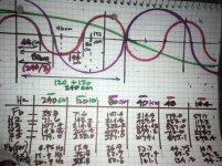
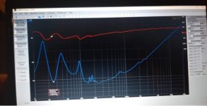
Experiment in folding segments vs ‘stub or absorber chambers of similar lengths. Buddy in Tennnesse built this, similar to a ROAR/ Paraflex i have been playing around with and also altered the large folding segment into a a split. exit and absorber chamber. roughly judging from
His numbers a folded absorber was formed to mimic the geometry of the harmonic impedances.
His numbers a folded absorber was formed to mimic the geometry of the harmonic impedances.
Attachments
Last edited:
- Home
- Loudspeakers
- Subwoofers
- What comes out of each side of a ‘compound horn’?